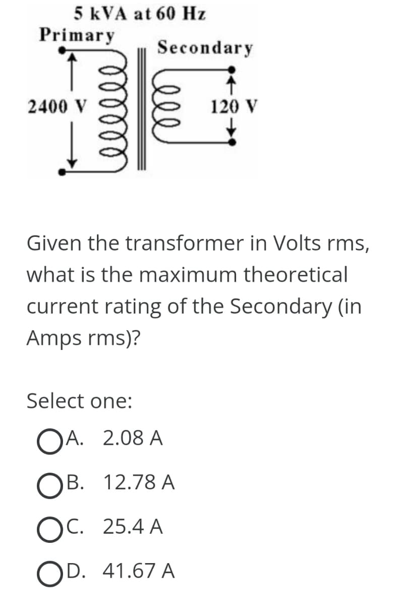
5 kVA at 60 Hz Primary 2400 V ееееее Secondary Given the transformer in Volts rms, what is the maximum theoretical 120 V current rating of the Secondary (in Amps rms)? Select one: OA. 2.08 A OB. 12.78 A OC. 25.4 A OD. 41.67 A


Q: Isc: UN 6e¾ be U₁zd 3V (A2 32²V/12 виз [₁2 A ib 7 V1₂ super mesh Visc
A:
Q: - V = ? 3√2 зл ми ми min 322 1.32 1.5√2 ← Samp/s oc on Determine the supply voltage in the following…
A: The circuit diagram,
Q: A 240V, 60 Hz source is suppling power the following loads Load 1: 10kVA @ pf = 0.55 lagging Load 2:…
A: Voltage V = 240VFrequency f = 60 Hz The loads areLoad 1: 10 kVA @ pf = 0.55 laggingLoad 2: 5 kVA @…
Q: 1- - Find the Fourier transformed f(x) 2²ix if + <x<) otherewise @ f(x) = { 0 O
A:
Q: A coil of resistance 25 and inductance 100 mH is connected in series with a capacitance of 0.12 µF…
A:
Q: Which of the following statements correctly describe the representation of power in an AC system…
A: Power Triangle is the representation of a right angle triangle showing the relation between…
Q: Given the following information for the circuit R = 2K, L = 200H and C = 312.5μF. Assume the switch…
A: Given:a circuit, with, we need to find:
Q: The switch in the circuit in (Figure 1) has been open a long time before closing at t = 0. Figure…
A: The given circuit isWe need to determine the expression of iL(t) for t≥0.
Q: A power transformer nameplate lists 2 kVA, 500/100 V, 60 Hz. If the 100 V number is the secondary…
A: In this question, we need to determine the current rating of secondary. We know current I= S/Vwhere…
Q: A O VAB в о 一个 11 www R1 ✓ 12 M R2 → 13 M R
A:
Q: I have a Non-Invering Op Amp with Vin, R1, Rf, and Vout. Rf has a resistor (R2) and a potentiometer…
A:
Q: Problem 4. The triangular current pulse shown in figure below is applied to a 375mH inductor. i (mA)…
A:
Q: Find the current across (a,b,c,d,e,f,g,h,i,j,k)
A: The given circuit isWe need to determine the current through (a,b,c,d,e,f,g,h,i,j,k).
Q: The expressions for the steady-state voltage and current at the terminals of the circuit seen in…
A: Given Data:A single-phase system with,The steady-state voltage The steady-state current To Find:a)…
Q: Derive the transfer function from the following block diagram: C(s) R(s) Ris) G₁ H₂ H₂ G₂ H₂ G₂ C(s)
A: Given:a control system, we need to find:Transfer function of the system using blick diagram…
Q: + v;(t) IO L с m R + vo(t)
A:
Q: For the given circuit where V= 24 V, use source transformation to find the current i.
A: For the given circuit the value of the current i needs to be calculated by using the source…
Q: The op amp circuit shown is ideal. The values for the circuit are as follows: +VCC = 12.0V, -VCC =…
A: Since you have posted the questions with multiple support. So we are supposed to answer 3 subpart.
Q: In circuit in (Figure 1), ig 200 cos 5000 mA. Part A Find the steady-state expression for v, in the…
A:
Q: 20 A 2-53.13° The active power = The reactive power = ↑ The apparent power = R = 3 Ω W + VR- W VAR…
A: Given circuit,Asked to find the,Active power P =?Reactive power Q =?Apparant power S =?Power factor…
Q: the answer to the last part was correct however the first two were incorrect, would you be able to…
A: Given circuit,Vg = 75 cos(5000t) volts,R = 200 ,Asked to find the,Magnitude of the voltage VoPhase…
Q: FIND I (t)
A: For the given circuit the value of the current through the capacitor needs to be calculated and the…
Q: Find Vc, IL and the energy stored in the capacitor and inductor in the circuit of the following…
A:
Q: The current at resonance in a series R-L-C circuit is 0.12mA. The circuit has an induc- tance of…
A:
Q: 8. Identify the components in this circuit. Resistance in Series www I V
A: Given circuit,Asked to identify the components.Note: “Since you have posted question with multiple…
Q: An e.m.f. whose instantaneous value at time t is given by v(t) = 283 sin (314t + π/4) volts is…
A: We need to find out active power for given voltage and current.
Q: Given the circuit in the figure, use superposition to obtain io. Take Vs = 22 V. Vs(+ 4Ω ww The…
A: The given circuit isWe need to determine the current io using super position theorem.Super position…
Q: 2.-) Analyze and find the transfer function of the circuit, make its graph in relation to: Vout vs…
A: According to the question, for the given circuit as shown belowWe need to analyze and find the…
Q: Calculate the average power of the signal g(t) in the figure.
A: A periodic signal is given byWe need to find the average power of the signal g(t).
Q: R₁ www www R₂ Rc Bernuarta RE +Vcc En la figura presentada Vcc = 14 V, R₁ = 498 k2, R₂ = 479 kN, Rċ…
A:
Q: a. Find the charge on the capacitor at t = 30 us. b. Find the voltage on the capacitor at t = 50 µs.…
A: For the given value of capacitor along with the current, the value of charge on the capacitor,…
Q: A Series R-L-c circueit has sinusoidas input voltage is 12 V. If Inductance L=20mH, Resistance R =…
A:
Q: 1-If $ D dl = 0 is true on a surface, which of the following cannot be said. a)The sum of the…
A: According to the question,if is true on a surface, then which of the following can not be saida)The…
Q: A lead wire with a radius of 0.5 mm and a length of 20 cm is connected to a potential difference of…
A: Given diagram,
Q: 100mA W 680 220 20V 330 WWW V +
A: source transformation
Q: a. A digital signal b(n) is defined as b(n) = 0, n<0 n, 0≤n≤1 2-n,1≤n<4 0, n ≥ 4 | Calculate the…
A:
Q: 3.-) Determine Iz and Pz for the Zener regulator circuit. +1 VIN 30V R1 500 * D1 20V R2 1.5k
A:
Q: How does a bridge differ from a switch in terms of operation?
A: A bridge and a switch are two distinct networking devices that operate at different layers of the…
Q: Question 12: Find the even and odd parts of the function a) g(t) = 4 cos 37 b) g(n) = 4…
A: We need to find out eben and odd part of given signal.
Q: Use the node-voltage method to find the steady-state expression for vo(t) in the circuit in (Figure…
A: The circuit diagram,
Q: In the following electrical circuit, the resistors R₁ have a resistance of 20 . R₂ exhibits a…
A:
Q: Plot the root locus (assuming proportional feedback) of the following ns a) G(s) = 5+2.5 5-6.0 b)…
A: Given:
Q: A battery is connected in series to a capacitor and a resistor. At time = Os the capacitor is…
A: Given:A circuit, with capacitor initially uncharged. At t=0 the capacitor is uncharged. After some…
Q: Find the total impedance |ZT|= Find the total current ||s] = = Find the total complex power in…
A: For the given network the value of the total impedance, total current and complex power needs to be…
Q: Problem 1: Question Consider the circuit diagram below. Es 12 kV R₁ •38 ΚΩ RL a) If the efficiency…
A: The circuit diagram,The efficiency,
Q: #1 For the circuit below, (a) Find the h parameters. (b) Find the g parameters. V₁ 5Ω 20Ω 15 ΩΣ 12 +…
A: The circuit diagram,
Q: a)Find the fourier transform of the signals. 2^n sin(pi*n /4) u[-n]
A: Since you have posted multiple questions, we will provide the solution only to the first question as…
Q: (s) Ge G₁ H₁ H₂ D(s) G₂ G₂ C(s) For the following block diagram derive the closed loop transfer…
A: given
Q: Find the Voltage from node n1,n2,n3,n4,n5
A: The given circuit isWe need to determine the voltages at nodes n1, n2, n3, n4 and n5.
Q: 5. In LQR controller technique decreasing value of the element q12 in Q matrix can a. Increase rise…
A: The answer is a. Increase rise time.The matrix in LQR controller technique represents the state…


Trending now
This is a popular solution!

Step by step
Solved in 3 steps with 3 images

- Under balanced operating conditions, consider the three-phase complex power delivered by the three-phase source to the three-phase load. Match the following expressions, those on the left to those on the right. (i) Realpower, P3 (a) (3VLLIL)VA (ii) Reactive power, Q3 (b) (3VLLILsin)var (iii) Total apparent power, S3 (c) (3VLLILcos)W (iv) Complex power, S3 (d) P3+jQ3 Note that VLL is the rms line-to-line voltage, IL is the rms line current, and is the power-factor angle.The instantaneous power absorbed by the load in a single-phase ac circuit, for a general R LC load under sinusoidal-steady-state excitation. is (a) Nonzero constant (b) Zero (c) Containing double-frequency componentsConsider a single-phase load with an applied voltage v(t)=150cos(t+10)volts and load current i(t)=5cos(t+50)A. (a) Determine the power triangle. (b) Find the power factor and specify whether it is lagging or leading. (c) Calculate the reactive power supplied by capacitors in parallel with the load that correct the power factor to 0.9 lagging.
- Consider a load impedance of Z=jwL connected to a voltage and V let the current drawn be I. (a) Develop an expression for the reactive power Q in terms of ,L, and I, from complex power considerations. (b) Let the instantaneous current be i(t)=2Icos(t+). Obtain an expression for the instantaneous power p(t) into L, and then express it in terms of Q. (c) Comment on the average real power P supplied to the inductor and the instantaneous power supplied.The voltage v(t)=359.3cos(t)volts is applied to a load consisting of a 10 resistor in parallel with a capacitive reactance XC=25. Calculate (a) the instantaneous power absorbed by the resistor, (b) the instantaneous power absorbed by the capacitor. (c) the real power absorbed by the resistor, (d) the reactive power delivered by the capacitor, and (e) the load power factor.The total instantaneous power absorbed by a three-phase motor (under balanced steady-state conditions) as well as a balanced three-phase impedance load is (a) A constant (b) A function of time
- A single-phase, 120V(rms),60Hz source supplies power to a series R-L circuit consisting of R=10 and L=40mH. (a) Determine the power factor of the circuit and state whether it is lagging or leading. (b) Determine the real and reactive power absorbed by the load. (c) Calculate the peak magnetic energy Wint stored in the inductor by using the expression Wint=L(Irms)2 and check whether the reactive power Q=Wint is satisfied. (Note: The instantaneous magnetic energy storage fluctuates between zero and the peak energy. This energy must be sent twice each cycle to the load from the source by means of reactive power flows.)A source supplies power to the following three loads connected in parallel: (1) a lighting load drawing 10kW. (2) an induction motor drawing 10kVA at 0.90 power factor lagging, and (3) a synchronous motor operating at 10hp,85 effIciency and 0.95 power factor leading (1hp=0.746kW). Determine the real, reactive, and apparent power delivered by the source. Also, draw the source power triangle.A residential four-wire system supplies power at 220 V rms to the following single-phase appliances: On the first phase, there are ten 60-W bulbs. On the second phase, there is a 1-kW vacuum cleaner with a power factor of 0.9. On the third phase, there are ten 23-W compact fluorescent lamps with power factor of 0.61. Find a. The current in the neutral wire. b. The real, reactive, and apparent power for each phase.
- Consider a 10 kVA, 200/400 V, 50 HZ: single-phase tranformer has the folloving test results:0.C. test: 200 V, 0.6A, 63 W (L.V.side)S.C. test : 20 V, 25A, 85 W (H.V. side)Deternine:i- The eficiengy at 75 % offiull-load at 0.9 leading power factor.ii -The secondary terminal voltage on fill-load at tunity power factonA star connected load with real impedance ZL= 1-j1 Ohm per phase is connected to the secondary of a three-phase Ynyn0 connected transformer. The equivalent impedance per reduced phase of the transformer to the primary is Zeq1= 1+j5 Ohm. The nominal primary voltage is V1Ln= 5920 V and the conversion ratio is a= 10. what is the amplitude of the actual voltage falling on one phase of the specified load? (simplified equivalent circuit will be used).Which termination would result to a phase change of 180 degrees at the load if Zo = 100 ohm? a. 50 ohm b. short circuit c. 75 ohm d. all of these What is the purpose of impedance matching? a. maximum return loss b. maximum SWR c. maximum load power d. maximum reflection A short piece of transmission line that may be open or shorted and used for impedance matching purposes. a. converter b. decoder c. stub d. transformer