1 1 Load parallel data 6.7 Draw the logic diagram of a four-bit register with four D flip- flops and four 4×1 multiplexers with mode selection inputs s1 and so. The register operates according to the following function table. (HDL ―see Problem 6.35(e), (f)) s1 s0 Register Operation 0 0 No change 10 Complement the four outputs 01 Clear register to 0 (synchronous with the clock)
1 1 Load parallel data 6.7 Draw the logic diagram of a four-bit register with four D flip- flops and four 4×1 multiplexers with mode selection inputs s1 and so. The register operates according to the following function table. (HDL ―see Problem 6.35(e), (f)) s1 s0 Register Operation 0 0 No change 10 Complement the four outputs 01 Clear register to 0 (synchronous with the clock)

Chapter22: Sequence Control
Section: Chapter Questions
Problem 6SQ: Draw a symbol for a solid-state logic element AND.

Related questions
Question

Transcribed Image Text:1 1 Load parallel data
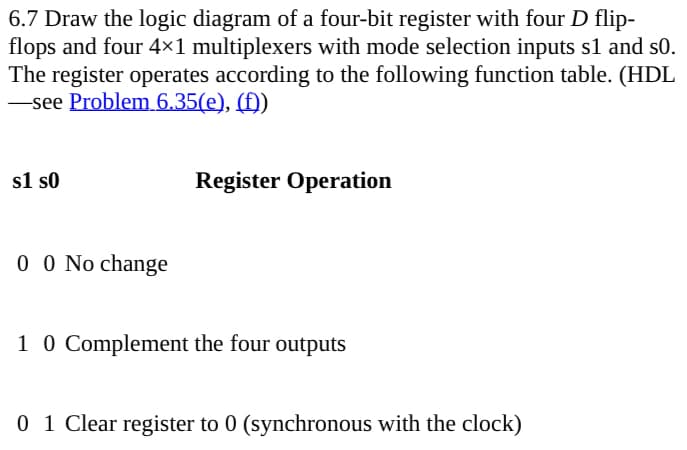
Transcribed Image Text:6.7 Draw the logic diagram of a four-bit register with four D flip-
flops and four 4×1 multiplexers with mode selection inputs s1 and so.
The register operates according to the following function table. (HDL
―see Problem 6.35(e), (f))
s1 s0
Register Operation
0 0 No change
10 Complement the four outputs
01 Clear register to 0 (synchronous with the clock)
Expert Solution
This question has been solved!
Explore an expertly crafted, step-by-step solution for a thorough understanding of key concepts.

Step by step
Solved in 2 steps

Recommended textbooks for you