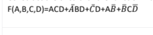
Construct the circuit for the function F using two input gates only. F(A,B,C,D)=ACD+ÃBD+ČD+AB+BCD


Q: Design a full adder by designing the truth table, minimizing the truth table using K-Maps, and…
A: The full adder can be designed by using the Exor gate,AND gate and OR gate.
Q: The photo has the input of a D-latch. Determine the value of Q at 1, 2, 3, and 4. Please explain…
A: Determine the value of Q at 1, 2, 3, and 4.
Q: Find the full zero input responses for the LTI systems with given initial conditions. Initial…
A: Note: We are authorized to answer three sub parts at a time, since you have not mentioned which part…
Q: To design a counter which count in the following sequence 0,1,3,5,7 by using T-F.F, the input of…
A: The counting Sequence for the counter is 0,1,3,5,7 and Repeats..
Q: Design a circuit diagram for the following comparator system that takes three 3-bit binary numbers…
A: We need to design a circuit diagram for the following comparator system that takes 3-bit binary…
Q: Verify the differentiation in s property (3.21); that is, dX(s) - tx (t) ds
A: In the following section, the differentiation in s property of the Laplace transform has been…
Q: (1) Design the following combinational circuits. (a) Takes 3-bit input and outputs the 3-bit…
A: As per our guidelines we are supposed to be answer the first question only. Kindly repost the other…
Q: Question 4 Design a combinational circuit that converts a four-bit gray code to BCD code
A: Binary Coded Decimal (BCD) is a way we can store the decimal numbers in the binary form. The number…
Q: A combinational switching network, has four inputs (a,b,c,d) and the output is the integer of (half…
A: A combinational switching network, has four inputs (a,b,c,d) and the output is the integer of (half…
Q: The input-output model for a system is given by ÿ(t) + 7y(t) + 12y(t) = 3u(t) The corresponding…
A: Given: The input output model of a system is given by, y"t+7y't+12yt=3ut.
Q: Design a 3- bit combinational circuit 2's complement. I.e (The output generates the 2's complement…
A: First we will find out the expression for output from kmap .
Q: Design a 3- bit combinational circuit 2’s complement. i.e (The output generates the 2’s complement…
A: First we will draw truth table ,then we will find out expression for output from k map .
Q: Use convolution theorem to find zero state response if input is x(t) = d dt2 Y(t) +3- d? t) = -2 d d…
A:
Q: uppose a circuit is required to recognize the 3-bit pattern (1100), and output (z=1) whenever it…
A:
Q: Find the Transfer Function of the system modeled by the follo d²y(t) dt² dy(t) dt d³ y(t) dt3 +3-…
A: Given data, Differential equation is given as, d3ytdt3+3d2ytdt2+2dytdt=d2xtdt2+3xt
Q: 1. Given a three inputs A, B, and C. Design the circuit that has output (1) only when A,B,C are :…
A: Given, The output is "1" when inputs A,B & C are (000),(100),(101),(110) and (111). The minimal…
Q: d²y du 5. A control system is described by +3x+2y= + u. Where 'u' is input dt² dt and 'y' is output.…
A: Apply laplace transform to the differential equation. Ratio of laplace transform of output to the…
Q: du 5. A control system is described by d²y dy +3 +2y= dt dt² dt and 'y' is output. The transfer…
A: Use following properties of transfer function LTd2ydt2= S2ysLTdydt= Sys Apply laplace transform to…
Q: Interept the following boolean expressions and reduce it to one leteral also draw its combinational…
A:
Q: 1. A majority circuit is a combinational circuit whose output is equal to 1 if the input variable…
A:
Q: Construct the circuit that produce the output: Z = A-C+A·B+A·B•č.
A: We need to construct logic diagram
Q: Find the first Foster form of the driving-point func- tion of 2(s + 2) (s + 5) (s + 4) (s + 6) Z(s)…
A:
Q: Design a simpler circuit for the given logical diagram by simplifying the output F.
A:
Q: 42] Example 6 MS] Try to find the output equation yourself M8] M7] 4) (1] X[n] yln) T13]
A:
Q: We want to design a combinational circuit that computes the function: { 4r +1 r<3 H-1 r23 F(z) =…
A: As we have given: Fx=4x+1 x<3x-1 x≥3 For 3 bit x x ranges from (000) 0 to (111) 7 Let's…
Q: Consider the following circuit to answer the below questions while assuming signed 2s complement…
A:
Q: Please convert the ff. breadboard circuit into a circuit diagram
A:
Q: The code to convert the state space model to transfer function model is : >>(num,den)=…
A: False
Q: A comparator shown in the circuit below is used to pick the smaller of the two 4-bit numbers A or B.
A: We need maxA,Bi.e if A>B⇒out=A=D1 A<B⇒out=B=D0
Q: A combinational switching network, has four inputs (a,b,c,d) and the output is the integer of ( half…
A: Draw the table for input and assign 0 &1 for Valid input and don't care for invalid input. Then…
Q: The BCD equivalent and binary equivalent of the hexadecimal number C are same. Select one: O True O…
A:
Q: The circuit F(A, B,C) = II(1,4,6) is designed using 1- Mux 8 - to be the value of the inputs
A: In POS form, pairing of zeroes is done and each individual term is called maxterm. In maxterm, first…
Q: The output sum, S and carry, C has equation of: Sum (A1, A2, A3) = ∏ (0, 3, 5, 6) Carry (A1, A2, A3)…
A:
Q: Compute the 8-point DFT of a sequence x(n) - (1/a, 1/b, 1/c, 1/d, 0, 0, 0,0) using radix-2 DIT FFT
A: xn=1a,1b,1c, 1d,0,0,0,0
Q: ✓ For the system represented by the following. Find the output. for the 0.3 Z X(Z) unit step…
A:
Q: or F kn. The 'Transfer Fcn ' block can be extracted from 'Commonly Used Blocks' library. If the…
A: 1) The transfer fcn block can be extracted from commonly used blocks library true
Q: Find the Transfer Function of the system modele by d²y(t) dt² d³y(t) dt3 Select one: +38 OH(s) +35³…
A: Given data, Differential equation is given as, d3ytdt3+3d2ytdt2dt+2dytdt=d2xtdt+3xt
Q: (a) A, B, C, D are the input variables in the truth table shown below. F1 – F7 are output variables.…
A: (a) From the given truth table, write the min-term expression for the function F2. Draw the K-map…
Q: 12.Determine the complement of the given function F=(a'+b')(a'+b)
A:
Q: Design a combinational circuit that converts excess-3 output code to the BCD input.
A: K-map is used to minimized the expression . It is represented as table of rows or column having…
Q: Design a combinational circuit that takes a 4-bit ABCD number as input and produces the sum of the…
A: Multiplexer (MUX) Circuit : It is a combinational circuit. It has (2^n) no. of inputs, 1 outputs and…
Q: Takes 3-bit input and outputs 1 when the number of 1's in the input number is smaller than the…
A: Since you have asked multiple questions in a single request, we will be answering only the 1st…
Q: Consider the following circuit to answer the below questions while assuming signed 2s complement…
A:
Q: Design a combinational circuit that calculates the function Y = 8X - 3, where X is an 8-bit signed…
A: Encoder: An encoder is a device that converts the analog signal into digital bits form. The…
Q: The circuit F(A, B) = E(1,2) is designed using 1- Mux 4 - to be the value of the inputs
A: A combinational circuit is one in which the various gates in the circuit, such as the encoder,…
Digital Circuits Question

Given Function:

Step by step
Solved in 2 steps with 2 images


- Implement the following function using a 8x1 multiplexer. Properly label inputs and outputs.F(A,B,C,D)=A'C'D+AC'+AD'+B'CD'calculate the gate input of F=AB + C(D+E)Given the following image, which BCD codes which output will be high for the following input conditions on a BCD to decimal converter? BCD input code Do-0₂ ABCD=0010 ABCD=0101 06 ABCD=1001 Ő₂ 0₁
- Single-choice (a), (b), (c), or (d). 1. A half-adder is characterized by (a) two inputs and two outputs (c) two inputs and three outputs 2. A full-adder is characterized by (a) two inputs and two outputs (c) two inputs and three outputs 3. The inputs to a full adder are A = (b) three inputs and two outputs (d) two inputs and one output (b) three inputs and two outputs (d) two inputs and one output 1, B = 0, C = 1. The outputs are = 1, Cout = 0 (a) = 0, Cout=1 (b) (c) = 0, Cout = 0 (d) Σ = 1, Cout = 1 4. A 3-bit parallel adder can add (a) three 2-bit binary numbers (e) three bits at a time (b) two 3-bit binary numbers (d) three bits in sequence 5. To expand a 2-bit parallel adder to a 4-bit parallel adder, you must (a) use two 2-bit adders with no interconnections (b) use two 2-bit adders and connect the sum outputs of one to the bit inputs of the other (e) use four 2-bit adders with no interconnections (d) use two 2-bit adders with the carry output of one connected to the carry input…This subject is digital signal processing of ece pls solve neatly and faster thanks Solve 2nd partFor the 4-bit comparator in the Figure, plot each output waveform for the inputs shown. The outputs are active-HIGH. COMP Ay 3. A>B A>B Voc A-B A-8 AConstruct a four-bit comparator with inputs A [3:0] and B [3:0] using a subtractor. The comparator circuit should identify the following cases as active-high outputs: A[3:0] =B[3:0] A[3:0] > B[3:0] A[3:0]Q8 [4-63(a)] Write the AHDL code to implement a comparator such that the output z is LOW only when the input digital_value is between 6 and 11 (inclusive).6674 in octal equal to . .in hexadecimal O a. 1C x1+ 1A x10 +C x100 O b. 2C x1+ 19 x10 +C x100 O c. Dx1+ B x10 +C x100 O d. C x1+ 1BX10 +C x100Solve for the output of the DAC in figure below if the waveforms representing a sequence of 4-bit numbers in figure below are applied to the inputs. Input DO is the least significant bit (LSB). 0 1 2 3 4 5 6 7 8 9 1011 12 13 14 15 200 kfN +5 V Do +5 V D, o 100 kN D, o 10 kN D 0 i O. 50 kN +5 V D2 +5 V Vout 25 kn D, o W- D3 Reverse the input waveforms to the DAC in the figure (D3 to DO, D2 to D1, D1 to D2, D0 to D3) and determine the output.Design a 5-bit adder-subtractor circuit using to illustrate the following operations: (a) 25-9 (b) 30 – 17The hexadecimal equivalent of a binary 0010111101111110 is 2F7E O 2F4E O 3F7E O 2F7F OSEE MORE QUESTIONSRecommended textbooks for youIntroductory Circuit Analysis (13th Edition)Electrical EngineeringISBN:9780133923605Author:Robert L. BoylestadPublisher:PEARSON
 Delmar's Standard Textbook Of ElectricityElectrical EngineeringISBN:9781337900348Author:Stephen L. HermanPublisher:Cengage Learning
 Programmable Logic ControllersElectrical EngineeringISBN:9780073373843Author:Frank D. PetruzellaPublisher:McGraw-Hill Education
 Fundamentals of Electric CircuitsElectrical EngineeringISBN:9780078028229Author:Charles K Alexander, Matthew SadikuPublisher:McGraw-Hill Education
 Electric Circuits. (11th Edition)Electrical EngineeringISBN:9780134746968Author:James W. Nilsson, Susan RiedelPublisher:PEARSON
 Engineering ElectromagneticsElectrical EngineeringISBN:9780078028151Author:Hayt, William H. (william Hart), Jr, BUCK, John A.Publisher:Mcgraw-hill Education,Introductory Circuit Analysis (13th Edition)Electrical EngineeringISBN:9780133923605Author:Robert L. BoylestadPublisher:PEARSONDelmar's Standard Textbook Of ElectricityElectrical EngineeringISBN:9781337900348Author:Stephen L. HermanPublisher:Cengage LearningProgrammable Logic ControllersElectrical EngineeringISBN:9780073373843Author:Frank D. PetruzellaPublisher:McGraw-Hill EducationFundamentals of Electric CircuitsElectrical EngineeringISBN:9780078028229Author:Charles K Alexander, Matthew SadikuPublisher:McGraw-Hill EducationElectric Circuits. (11th Edition)Electrical EngineeringISBN:9780134746968Author:James W. Nilsson, Susan RiedelPublisher:PEARSONEngineering ElectromagneticsElectrical EngineeringISBN:9780078028151Author:Hayt, William H. (william Hart), Jr, BUCK, John A.Publisher:Mcgraw-hill Education,