
Loose Leaf for Engineering Circuit Analysis Format: Loose-leaf
9th Edition
ISBN: 9781259989452
Author: Hayt
Publisher: Mcgraw Hill Publishers
expand_more
expand_more
format_list_bulleted
Videos
Textbook Question
Chapter 10.5, Problem 9P
With reference to the network shown in Fig. 10.19, find the input impedance Zin that would be measured between terminals: (a) a and g; (b) b and g; (c) a and b.
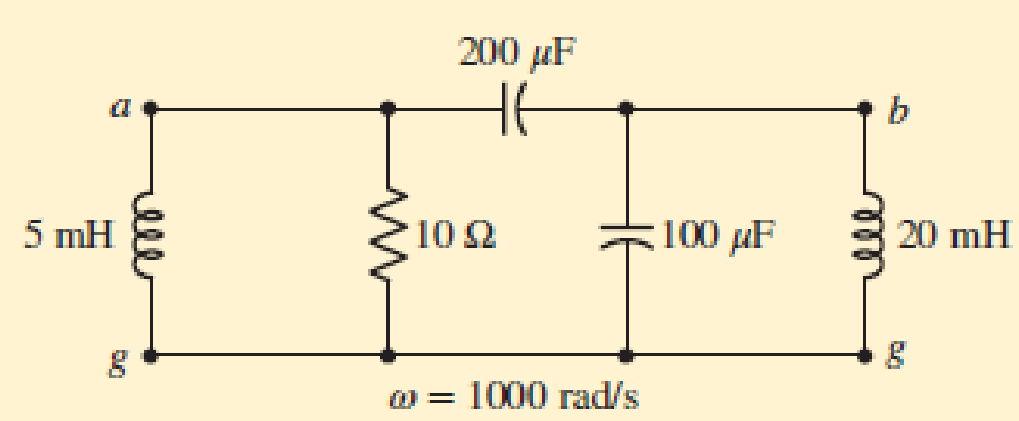
■ FIGURE 10.19
Expert Solution & Answer
Want to see the full answer?
Check out a sample textbook solution
Students have asked these similar questions
Use the system frequency of 60 kHz. (b) Find Vrms (gen) and inductive reactance. Attach your neat and complete solution. Thank you. ASAP!
Click here for image
↑ 11
Rm/
In this circuit, R1 = 502, 11-6 A, 12 = 2 A, Rm = 82./ has units of amperes.
Voc 10.2
112
Determine the Thevenin equivalent circuit at terminals a-b.
Rth = -5.6
State the values of the open-circuit voltage, Voc (in volts), and the equivalent resistance, Rth (in ohms), in the box below. Round your answers to one decimal place.
An example answer is shown below
b
Using the following sequence definitions,.
2. k0,1.2
Hk) =1. k= 3,4
elsewhere
2. k-0
1. k 1.2
0 elsewhere,
and xik)
a) Plot h(k) and x(k)
evaluate the digital convolution
b) Using the graphical method
c) Applying the convolution formula directly
Chapter 10 Solutions
Loose Leaf for Engineering Circuit Analysis Format: Loose-leaf
Ch. 10.1 - Find the angle by which i1 lags v1 if v1 = 120...Ch. 10.2 - Determine values for A, B, C, and if 40 cos(100t ...Ch. 10.2 - Let vs = 40 cos 8000t V in the circuit of Fig....Ch. 10.3 - Prob. 4PCh. 10.3 - If the use of the passive sign convention is...Ch. 10.4 - Let = 2000 rad/s and t = 1 ms. Find the...Ch. 10.4 - Transform each of the following functions of time...Ch. 10.4 - In the circuit of Fig. 10.17, both sources operate...Ch. 10.5 - With reference to the network shown in Fig. 10.19,...Ch. 10.5 - In the frequency-domain circuit of Fig. 10.21,...
Ch. 10.5 - Determine the admittance (in rectangular form) of...Ch. 10.6 - Use nodal analysis on the circuit of Fig. 10.23 to...Ch. 10.6 - Use mesh analysis on the circuit of Fig. 10.25 to...Ch. 10.7 - If superposition is used on the circuit of Fig....Ch. 10.7 - Prob. 15PCh. 10.7 - Determine the current i through the 4 resistor of...Ch. 10.8 - Select some convenient reference value for IC in...Ch. 10 - Evaluate the following: (a) 5 sin (5t 9) at t =...Ch. 10 - (a) Express each of the following as a single...Ch. 10 - Prob. 3ECh. 10 - Prob. 4ECh. 10 - Prob. 5ECh. 10 - Calculate the first three instants in time (t 0)...Ch. 10 - (a) Determine the first two instants in time (t ...Ch. 10 - The concept of Fourier series is a powerful means...Ch. 10 - Household electrical voltages are typically quoted...Ch. 10 - Prob. 10ECh. 10 - Assuming there are no longer any transients...Ch. 10 - Calculate the power dissipated in the 2 resistor...Ch. 10 - Prob. 13ECh. 10 - Prob. 14ECh. 10 - Prob. 15ECh. 10 - Express the following complex numbers in...Ch. 10 - Prob. 17ECh. 10 - Prob. 18ECh. 10 - Evaluate the following, and express your answer in...Ch. 10 - Perform the indicated operations, and express the...Ch. 10 - Insert an appropriate complex source into the...Ch. 10 - For the circuit of Fig. 10.51, if is = 2 cos 5t A,...Ch. 10 - In the circuit depicted in Fig. 10.51, if is is...Ch. 10 - Employ a suitable complex source to determine the...Ch. 10 - Transform each of the following into phasor form:...Ch. 10 - Prob. 26ECh. 10 - Prob. 27ECh. 10 - The following complex voltages are written in a...Ch. 10 - Assuming an operating frequency of 50 Hz, compute...Ch. 10 - Prob. 30ECh. 10 - Prob. 31ECh. 10 - Prob. 32ECh. 10 - Assuming the passive sign convention and an...Ch. 10 - The circuit of Fig. 10.53 is shown represented in...Ch. 10 - (a) Obtain an expression for the equivalent...Ch. 10 - Determine the equivalent impedance of the...Ch. 10 - (a) Obtain an expression for the equivalent...Ch. 10 - Determine the equivalent admittance of the...Ch. 10 - Prob. 40ECh. 10 - Prob. 41ECh. 10 - Find V in Fig. 10.55 if the box contains (a) 3 in...Ch. 10 - Prob. 43ECh. 10 - Prob. 44ECh. 10 - Design a suitable combination of resistors,...Ch. 10 - Design a suitable combination of resistors,...Ch. 10 - For the circuit depicted in Fig. 10.58, (a) redraw...Ch. 10 - For the circuit illustrated in Fig. 10.59, (a)...Ch. 10 - Referring to the circuit of Fig. 10.59, employ...Ch. 10 - In the phasor-domain circuit represented by Fig....Ch. 10 - With regard to the two-mesh phasor-domain circuit...Ch. 10 - Employ phasor analysis techniques to obtain...Ch. 10 - Determine IB in the circuit of Fig. 10.62 if and ....Ch. 10 - Determine V2 in the circuit of Fig. 10.62 if and ....Ch. 10 - Employ phasor analysis to obtain an expression for...Ch. 10 - Determine the current ix in the circuit of Fig....Ch. 10 - Obtain an expression for each of the four...Ch. 10 - Determine the nodal voltages for the circuit of...Ch. 10 - Prob. 59ECh. 10 - Obtain an expression for each of the four mesh...Ch. 10 - Determine the individual contribution each current...Ch. 10 - Determine V1 and V2 in Fig. 10.68 if I1 = 333 mA...Ch. 10 - Prob. 63ECh. 10 - Obtain the Thvenin equivalent seen by the (2 j) ...Ch. 10 - The (2 j) impedance in the circuit of Fig. 10.69...Ch. 10 - With regard to the circuit depicted in Fig. 10.70,...Ch. 10 - Prob. 67ECh. 10 - Determine the individual contribution of each...Ch. 10 - Determine the power dissipated by the 1 resistor...Ch. 10 - The source Is in the circuit of Fig. 10.75 is...Ch. 10 - Prob. 72ECh. 10 - (a) Calculate values for IL, IR, IC, VL, VR, and...Ch. 10 - In the circuit of Fig. 10.77, (a) find values for...Ch. 10 - The voltage source Vs in Fig. 10.78 is chosen such...Ch. 10 - For the circuit shown in Fig. 10.79, (a) draw the...Ch. 10 - For the circuit shown in Fig. 10.80, (a) draw the...Ch. 10 - (a) Replace the inductor in the circuit of Fig....Ch. 10 - Design a purely passive network (containing only...
Knowledge Booster


Learn more about
Need a deep-dive on the concept behind this application? Look no further. Learn more about this topic, electrical-engineering and related others by exploring similar questions and additional content below.Similar questions
- т 2. Consider the circuit is shown in the figure below. The circuit comprises a voltage supply, v(t), resistor (R), inductor (L) and capacitor (C). Let x1 = i and x2 = v. be the state variables for this system, where i and ve are the circuit current and capacitor voltage, respectively. For this system, a) Derive the loop equation, involving integro-differential equations, from first principles b) Write the state differential equations Write the state-space equation in matrix-vector form Sketch the signal-flow graph. c) Show all your work. L v(1)arrow_forward(ACADEMIC) 8205828page%3D1 The equivalent resistance RAR (in the figure) is: A O 62. 10. BO 10. 12. b. not possible to compute without Y to Delta conversion. C. bere to search S3一4arrow_forward10.23. Draw the block diagrams of both the direct forms I and II simulation diagrams for the systems with the following difference equations: (a) 2y[n]y[n 1] + 4y[n-2] = 5x[n] (b) 1 3]arrow_forward
- VOLTE ll O ON100% 10:48 + IMG_4550.jpg For the circuit shown, it is required to design a circuit with minimum losses. The value of n (the turns ratio) that maximizes the transferred power to the secondary coil is. (ABET assessment of outcome 2) 4000 2 1:n 120/0°V rms 10 Ω 0.1 O 0.0025 20 400 0.05 None of the above ellarrow_forwardPROBLEM Io.27 For the circuit shown in Figure 10.128, sketch and label vR versus time. Assume that v = K1 for a long time prior to t = 0 as illustrated in the figure. %3D Note that this problem can be solved in a number of simple steps by breaking the problem down into parts and solving each part. There are several ways to do this breakdown, all of roughly equal ease.arrow_forwardConsider the system Transfer Function as shown in Figure 1. Obtain the rise time t, peak time t, maximum overshoot Mp and settling time & when the system is subjected to a unit step input. Given; 3= 0.6 , w = 5 rad/sec E(s) C(3) S(S + 2(w) Figure 1arrow_forward
- 1. Consider the translational mechanical network system shown on the figure. A 1-N, f(t), si applied at t=0. If fv=1, find K and M such that the response is characterized by a 4-sec settling time and a 1-sec peak time. Also, what is the resulting %OS? 2. Given the translational mechanical system shown on the figure, where K=1 and f(t) is a unit step, find the values of M and fv to yield a response with 17% overshoot and a settling time of 10 seconds. f. r(1) M Karrow_forwardExample 10.6. The change of inductance for a moving-iron ammeter is 2µH/degree. The control spring constant is 5 x 10⁷ N-m/degree. The maximum deflection of the pointer is 100°, what is the current corresponding to maximum deflection ? (Measurement & Instrumentation Nagpur Univ. 1993)arrow_forward10.23. Draw the block diagrams of both the direct forms I and II simulation diagrams for the systems with the following difference equations: (d) y[n] 0.25(x[n] + x[n 1] + x[n- 2] + x[n- 3]) .... 00-6arrow_forward
- 7. (a) For step-down chopper circuit, source voltage Vs = 220 V, chopping period T = 2000' us, on period = 600 µs, load circuit parameters- R=12, L = 5 mH and E =24 V (9 Find whether load current is continuous or not. (ü) Calculate the value of average output current. füi) Compute the maximum and minimum values of steady state output currents.arrow_forwardPlease sholve for the i hat, j hat, at k hat. Sample solutions also indicated below.arrow_forwardConsider in the given system = 0.6 and wn = 5 rad/sec. Calculate the rise Time t,,peak time tp, maximum overshoot Mp, and settling time t, (for 2% & 5% criterion) when the system is subjected to a unit-step input. R(s) E(s) w7 s(s+ 25wn) C(s) 40) 0.5 4. Allowable tolerance 0.05 or 0.02arrow_forward
arrow_back_ios
SEE MORE QUESTIONS
arrow_forward_ios
Recommended textbooks for you
 Delmar's Standard Textbook Of ElectricityElectrical EngineeringISBN:9781337900348Author:Stephen L. HermanPublisher:Cengage Learning
Delmar's Standard Textbook Of Electricity
Electrical Engineering
ISBN:9781337900348
Author:Stephen L. Herman
Publisher:Cengage Learning
Introduction to Two-Port Networks; Author: ALL ABOUT ELECTRONICS;https://www.youtube.com/watch?v=ru2ItcD6unI;License: Standard Youtube License