
Fundamentals of Electric Circuits
6th Edition
ISBN: 9780078028229
Author: Charles K Alexander, Matthew Sadiku
Publisher: McGraw-Hill Education
expand_more
expand_more
format_list_bulleted
Videos
Textbook Question
Chapter 16.6, Problem 13PP
For what value of β is the circuit in Fig. 16.29 stable?
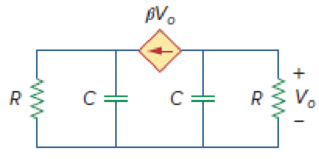
Figure 16.29
Expert Solution & Answer
Want to see the full answer?
Check out a sample textbook solution
Students have asked these similar questions
This allows
E ELECTRICAL
mple 3.8:
Consider the circuit in Fig. 16.12(a). Find the
value of the voltage
across the capacitor assuming that the value of vs(t) = 10u(t) V and
assume that at t = 0, -1 A flows through the inductor and +5 V is
across the capacitor.
19 2
EPARTM
%s (1)
ww
rell
(a)
5 H
0.1 F
INEERING
in with th
16.9 a. Design a hard limiter as shown in Fig. 16.15(a) by determining the values of R₁, R2, R3, R4, and R5. The
circuit should limit the negative output voltage to Vo(min) = -7 V and the positive voltage to Vo(max) =
9 V. The magnitude of the slopes after the break points should be less than or equal to 1 50. The diode
drop is vp = 0.7 V at ip = 0.1 mA. The DC supplies are given by VA-VB = 15 V.
P
b. Use PSpice/SPICE to plot the transfer characteristic. Assume Vcc= 15 V, -VEE = -15 V, and vs = -5 V
to 5 V. Use the PSpice/SPICE op-amp macromodel.
R₂=R₁
Vref=0V=
+Vcc
-VEE
D₂
R₂
R₂
Rs
For Probs. 16.10 through 16.14, use comparator LM111 and vs = 10 sin (2000) to plot the hysteresis
characteristic using PSpice/SPICE.
Given the following N-channel enhancement MOSFET circuit
1.5 MQ
R2
75 k2
Rp
D
Vop
10 V
I M2
39 k2
Rs
The data are VGSTH =1 V and k= 0.0125 mA / V.
%3D
%3D
1) The correct quadratic equation for solving VGs is
i)
0.4875VGS-0.025VGS- 3.5125 = 0
ii)
0.4875VGS + 0.025VGS - 3.5125 = 0
0.4875Ves- 1.975Ves- 3.5125 = 0
iv)
0.4875Ves + 1.975Ves - 4.4875 = 0
iii)
2) Ip is
34.39 µA
172.05 µA
19.36 µA
68.78 µA
ii)
111
iv)
3) Vos is
i)
ii)
ii)
iv)
2.16 V
8.76 V
6.08 V
7.52 V
Chapter 16 Solutions
Fundamentals of Electric Circuits
Ch. 16.2 - Determine vo(t) in the circuit of Fig. 16.6,...Ch. 16.2 - Prob. 2PPCh. 16.2 - Prob. 3PPCh. 16.3 - For the circuit shown in Fig. 16.12 with the same...Ch. 16.3 - Prob. 5PPCh. 16.3 - The initial energy in the circuit of Fig. 16.17 is...Ch. 16.4 - Prob. 7PPCh. 16.4 - Prob. 8PPCh. 16.4 - Prob. 9PPCh. 16.5 - Obtain the state variable model for the circuit...
Ch. 16.5 - Prob. 11PPCh. 16.5 - Prob. 12PPCh. 16.6 - For what value of is the circuit in Fig. 16.29...Ch. 16.6 - Prob. 14PPCh. 16.6 - Prob. 15PPCh. 16.6 - Synthesize the function Vo(s)Vin=2ss2+6s+10 using...Ch. 16 - Prob. 1RQCh. 16 - The current through an RL series circuit with...Ch. 16 - Prob. 3RQCh. 16 - Prob. 4RQCh. 16 - Prob. 5RQCh. 16 - Prob. 6RQCh. 16 - Prob. 7RQCh. 16 - Prob. 8RQCh. 16 - Prob. 9RQCh. 16 - Prob. 10RQCh. 16 - The current in an RLC circuit is described by...Ch. 16 - The differential equation that describes the...Ch. 16 - Prob. 3PCh. 16 - If R = 20 , L = 0.6 H, what value of C will make...Ch. 16 - The responses of a series RLC circuit are vc(t) =...Ch. 16 - Prob. 6PCh. 16 - Prob. 7PCh. 16 - Prob. 8PCh. 16 - Prob. 9PCh. 16 - The step responses of a series RLC circuit are Vc...Ch. 16 - The step response of a parallel RLC circuit is v =...Ch. 16 - Prob. 12PCh. 16 - Prob. 13PCh. 16 - Prob. 14PCh. 16 - For the circuit in Fig. 16.38. calculate the value...Ch. 16 - The capacitor in the circuit of Fig. 16.39 is...Ch. 16 - If is(t) = 7.5e2t u(t) A in the circuit shown in...Ch. 16 - Find v(t), t 0 in the circuit of Fig. 16.41. Let...Ch. 16 - The switch in Fig. 16.42 moves from position A to...Ch. 16 - Find i(t) for t 0 in the circuit of Fig. 16.43.Ch. 16 - In the circuit of Fig. 16.44, the switch moves...Ch. 16 - Find the voltage across the capacitor as a...Ch. 16 - Obtain v (t) for t 0 in the circuit of Fig....Ch. 16 - The switch in the circuit of Fig. 16.47 has been...Ch. 16 - Calculate v(t) for t 0 in the circuit of Fig....Ch. 16 - Prob. 26PCh. 16 - Find v (t) for t 0 in the circuit in Fig. 16.50.Ch. 16 - For the circuit in Fig. 16.51, find v(t) for t 0.Ch. 16 - Prob. 29PCh. 16 - Find vo(t), for all t 0, in the circuit of Fig....Ch. 16 - Prob. 31PCh. 16 - For the network in Fig. 16.55, solve for i(t) for...Ch. 16 - Using Fig. 16.56, design a problem to help other...Ch. 16 - Prob. 34PCh. 16 - Prob. 35PCh. 16 - Prob. 36PCh. 16 - Prob. 37PCh. 16 - The switch in the circuit of Fig. 16.61 is moved...Ch. 16 - Prob. 39PCh. 16 - Prob. 40PCh. 16 - Prob. 41PCh. 16 - Prob. 42PCh. 16 - Prob. 43PCh. 16 - Prob. 44PCh. 16 - Find v(t) for t 0 in the circuit in Fig. 16.68.Ch. 16 - Prob. 46PCh. 16 - Determine io(t) in the network shown in Fig....Ch. 16 - Prob. 48PCh. 16 - Find i0(t) for t 0 in the circuit in Fig. 16.72....Ch. 16 - Prob. 50PCh. 16 - In the circuit of Fig. 16.74, find i(t) for t 0.Ch. 16 - Prob. 52PCh. 16 - In the circuit of Fig. 16.76, the switch has been...Ch. 16 - Prob. 54PCh. 16 - Prob. 55PCh. 16 - Calculate io(t) for t 0 in the network of Fig....Ch. 16 - Prob. 57PCh. 16 - Prob. 58PCh. 16 - Find vo(t) in the circuit of Fig. 16.82 if vx(0) =...Ch. 16 - Prob. 60PCh. 16 - Prob. 61PCh. 16 - Using Fig. 16.85, design a problem to help other...Ch. 16 - Consider the parallel RLC circuit of Fig. 16.86....Ch. 16 - The switch in Fig. 16.87 moves from position 1 to...Ch. 16 - For the RLC circuit shown in Fig. 16.88, find the...Ch. 16 - For the op amp circuit in Fig. 16.89, find v0(t)...Ch. 16 - Given the op amp circuit in Fig. 16.90, if v1(0+)...Ch. 16 - Prob. 68PCh. 16 - Prob. 69PCh. 16 - Using Fig. 16.93, design a problem to help other...Ch. 16 - Prob. 71PCh. 16 - The transfer function of a system is H(s)=s23s+1...Ch. 16 - Prob. 73PCh. 16 - Design a problem to help other students better...Ch. 16 - Prob. 75PCh. 16 - For the circuit in Fig. 16.95, find H(s) =...Ch. 16 - Obtain the transfer function H(s) = VoVs for the...Ch. 16 - Prob. 78PCh. 16 - For the circuit in Fig. 16.97, find: (a) I1/Vs (b)...Ch. 16 - Refer to the network in Fig. 16.98. Find the...Ch. 16 - Prob. 81PCh. 16 - Prob. 82PCh. 16 - Refer to the RL circuit in Fig. 16.101. Find: (a)...Ch. 16 - A parallel RL circuit has R = 4 and L = 1 H. The...Ch. 16 - Prob. 85PCh. 16 - Prob. 86PCh. 16 - Prob. 87PCh. 16 - Prob. 88PCh. 16 - Develop the state equations for the circuit shown...Ch. 16 - Prob. 90PCh. 16 - Prob. 91PCh. 16 - Prob. 92PCh. 16 - Prob. 93PCh. 16 - Prob. 94PCh. 16 - Prob. 95PCh. 16 - Prob. 96PCh. 16 - A system is formed by cascading two systems as...Ch. 16 - Determine whether the op amp circuit in Fig....Ch. 16 - It is desired realize the transfer function...Ch. 16 - Prob. 100PCh. 16 - Prob. 101PCh. 16 - Synthesize the transfer function...Ch. 16 - Prob. 103CPCh. 16 - Prob. 104CPCh. 16 - Prob. 105CP
Knowledge Booster


Learn more about
Need a deep-dive on the concept behind this application? Look no further. Learn more about this topic, electrical-engineering and related others by exploring similar questions and additional content below.Similar questions
- The A matrix of a state space model has eigenvalues: [0.45 2.1j, -3.1] What conclusion can be drawn about the system stability and oscillations? O unstable and oscillates O stable and does not oscillate O stable and oscillates O unstable and does not oscillatearrow_forwardAhalysis II- EE202/CE202-03 - Spring 2per*: arses / Linear Circuit Analysis II - EE202/CE202 - 03 - Spring 2021 ** / 2 May - 8 May / ICA2 (10%) 05/05/2021 @ 9 One pole on the left hand side of the S-plane is enough to make the transfer function stable. Select one: O True O False Next page re Assessment 4 (project report outline) al Steady State (SSS) response Jump to... ICA2 (10%) 05/05/2. hp f1o fu fg 立arrow_forwardo(t) = [ce-at cosßt - e-atsinft (cosßt + sinßt) B-Assume that 2e-sinßt + becos est (cosßt-singt) "C Find a, b, c, B, and a such that (t) is a state-transition matrix and Isl-A=5³+5+ hown in Fig.6, in which the PID controller is usedarrow_forward
- s Using the analysis DFT equation, if n = 5 and N 8, then X(4) can be written as: O a z(5)e 5* Ob I(5)e 1 (5)e Od r(4)e 7arrow_forward1. Use 2's complement method to prove that (FA)16-(DC)16=(36), HASIN ALAM FDE 4212021arrow_forward16.6 Design an output voltage-clamping circuit as shown in Fig. 16.14(a) so that the slope of the transfer char- acteristic is S = vo vs = 20, Vo(max) = 6.7 V, and Vo(min) = -8.7 V. Determine the zener voltages Vzi and V22. Assume Vp = 0.7 V. P S +== Vd A = ∞ I M R₁ Vx RE V22 Vz1 Voarrow_forward
- Choose the values of R1 and R2 in Fig. P16.133 to set I3 = 300 A and I1 = 75 A if VCC = VEE = 15 V. What is I2? Q136: (a) Based on the schematic in Fig. 16.46, what are the minimum values of VCC and VEE needed for proper operation of A741 amplifier? (b) What are the minimum values of VCC and VEE needed to have at least a ±1-V common-mode input range in the amplifier?arrow_forward2. Write the mathematical equations for the mechanical system given. Also find the transfer function X2(s)/F(s) of the given system. ft) K1 M1 B12 K2 M2 B2arrow_forwardWhich of the following is the expression defining the given circuit? (Z and A are LSB. U1 is 8x1 multiplexer integrated. ∏ is the product symbol.) A Q=∏(0,2,3,5,6,7) B Q=∏(0,1,3,4,5,6) C Q=∏(1,2,3,4,5,7) D Q=∏(0,1,2,4,6,7) E Q=∏(0,1,2,3,5,7)arrow_forward
- Give the minimal expression for the output fin the following circuit: 0 0 1 1 f 0 0 0 0 195 A WNTO O 1 2 3 4 6 7 S1 SO S2 X Y Z Select one: XY O XZ YZ XYZ None of these answers is correct.arrow_forwardResolve in a clear and orderly manner.DC AnalysisAC analysisEquivalent circuiarrow_forwardThe compensator circuit (passive if possible) will be made, which is given the function at the bottom. If R1= 0.1 MOhm, which is C? G6) = (s+5) 16 - A) 20 mikroF O B) 0.2 mikroF OC) 0.02 mikroF OD) 20 milliF E) 2 mikroFarrow_forward
arrow_back_ios
SEE MORE QUESTIONS
arrow_forward_ios
Recommended textbooks for you
 Introductory Circuit Analysis (13th Edition)Electrical EngineeringISBN:9780133923605Author:Robert L. BoylestadPublisher:PEARSON
 Delmar's Standard Textbook Of ElectricityElectrical EngineeringISBN:9781337900348Author:Stephen L. HermanPublisher:Cengage Learning
 Programmable Logic ControllersElectrical EngineeringISBN:9780073373843Author:Frank D. PetruzellaPublisher:McGraw-Hill Education
 Fundamentals of Electric CircuitsElectrical EngineeringISBN:9780078028229Author:Charles K Alexander, Matthew SadikuPublisher:McGraw-Hill Education
 Electric Circuits. (11th Edition)Electrical EngineeringISBN:9780134746968Author:James W. Nilsson, Susan RiedelPublisher:PEARSON
 Engineering ElectromagneticsElectrical EngineeringISBN:9780078028151Author:Hayt, William H. (william Hart), Jr, BUCK, John A.Publisher:Mcgraw-hill Education,
Introductory Circuit Analysis (13th Edition)
Electrical Engineering
ISBN:9780133923605
Author:Robert L. Boylestad
Publisher:PEARSON
Delmar's Standard Textbook Of Electricity
Electrical Engineering
ISBN:9781337900348
Author:Stephen L. Herman
Publisher:Cengage Learning
Programmable Logic Controllers
Electrical Engineering
ISBN:9780073373843
Author:Frank D. Petruzella
Publisher:McGraw-Hill Education
Fundamentals of Electric Circuits
Electrical Engineering
ISBN:9780078028229
Author:Charles K Alexander, Matthew Sadiku
Publisher:McGraw-Hill Education
Electric Circuits. (11th Edition)
Electrical Engineering
ISBN:9780134746968
Author:James W. Nilsson, Susan Riedel
Publisher:PEARSON
Engineering Electromagnetics
Electrical Engineering
ISBN:9780078028151
Author:Hayt, William H. (william Hart), Jr, BUCK, John A.
Publisher:Mcgraw-hill Education,
Systems and Simulation - Lecture 3: Modelling of Mechanical systems; Author: bioMechatronics Lab;https://www.youtube.com/watch?v=fMcDdyoC9mA;License: Standard Youtube License