Essential University Physics (3rd Edition)
3rd Edition
ISBN: 9780134202709
Author: Richard Wolfson
Publisher: PEARSON
expand_more
expand_more
format_list_bulleted
Videos
Textbook Question
Chapter 25.2, Problem 25.2GI
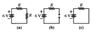
Rank front highest to lowest the voltages across the identical resistors R at the top of each circuit shown, and give the actual voltage for each. In (a) the second resistor has the same resistance R, and in (b) the gap is an open circuit (infinite resistance).
Expert Solution & Answer
Want to see the full answer?
Check out a sample textbook solution
Students have asked these similar questions
Figure given below displays two circuits with a charged capacitor that is to be discharged
through a resistor when a switch is closed. In figure(a), R1 = 16 Q and C1= 8 µF. In figure(b), R2
= 12 Q and C2 = 9 µF. The ratio of the initial charges on the two capacitors is q 02 /g01 = 10/2.
At time t = 0, both switches are closed. At what time t do the two capacitors have the same
charge? (Your result must be in multiples of 10 -4 s and include 2 digit after the decimal point.
That means if you get a result of a 9.22 x 10 -4 just type 9.22 in the answer box. Maximum of 5%
of error is accepted in your answer.)
-
The figure shows a direct current circuit. Assume that for the five external resistors we have
R₁ R₂ = R4 = Rm = R and R3 = R/2. What is the equivalence resistance from the point
a to point d. (Note that you can assume that the internal resistance of the voltage source is
zero.)
=
r
E
b
R₁
Rm
R3
a
d
R2
4
C
In the circuit shown the branch currents I1 and I3 are 5/7 A, and 2A, respectively and the unknown emf is 12.6 V. What is the potential difference across the top right 2 ohm resistor?
Chapter 25 Solutions
Essential University Physics (3rd Edition)
Ch. 25.1 - The figure shows three circuits. Which are...Ch. 25.2 - Rank front highest to lowest the voltages across...Ch. 25.2 - The figure shows all four possible combinations of...Ch. 25.2 - The figure shows a circuit with three identical...Ch. 25.3 - Which circuit(s) cannot be analyzed using series...Ch. 25.4 - All resistors in the figure have the same value...Ch. 25.5 - A capacitor is charged to 12 V and then connected...Ch. 25 - Are household electrical outlets connected in...Ch. 25 - All the resistors in Fig. 25.24 have the same...Ch. 25 - Can the voltage across a batterys terminals differ...
Ch. 25 - Can the voltage across a batterys terminals he...Ch. 25 - In some cities, streetlights are wired in such a...Ch. 25 - When the switch in Fig. 25.25 is open, whats the...Ch. 25 - Two identical resistors in series dissipate equal...Ch. 25 - When a large electric load such as a washing...Ch. 25 - How would you connect a pair of equal resistors...Ch. 25 - You have a battery whose voltage and internal...Ch. 25 - A student whos confused about voltage and current...Ch. 25 - A student whos confused about voltage and current...Ch. 25 - Sketch a circuit diagram for a circuit that...Ch. 25 - Sketch a diagram for a circuit consisting of two...Ch. 25 - Resistors R1 and R2 are in series, and the series...Ch. 25 - Whats the emf of a battery that delivers 27 J of...Ch. 25 - A 1.5-V battery stores 4.5 kJ of energy. How long...Ch. 25 - If you accidentally leave your car headlights...Ch. 25 - A 47-k resistor and a 39-k resistor are in...Ch. 25 - What resistance should you place in parallel with...Ch. 25 - A defective starter motor draws 300 A from a cars...Ch. 25 - Find the internal resistance of the battery in...Ch. 25 - When a 9-V battery is temporarily short-circuited,...Ch. 25 - You have a 1.0-, a 2.0-, and a 3.0- resistor. What...Ch. 25 - Find all three currents in the circuit of Fig....Ch. 25 - Prob. 26ECh. 25 - Find all three currents in the circuit of Fig....Ch. 25 - Prob. 28ECh. 25 - An ammeter with 100- resistance is inserted in the...Ch. 25 - A new mechanic foolishly connects an ammeter with...Ch. 25 - Show that the quantity RC has the units of time...Ch. 25 - If capacitance is in F, what will he the units of...Ch. 25 - Show that a capacitor is charged to approximately...Ch. 25 - An uncharged 10-F capacitor and a 470-k resistor...Ch. 25 - Find an expression for the voltage across the...Ch. 25 - In Fig. 25.28, all resistors have the same value,...Ch. 25 - In Fig. 25.28, take all resistors to be 1 k Find...Ch. 25 - Three 1.5-V batteries, with internal resistances...Ch. 25 - A partially discharged car battery can be modeled...Ch. 25 - Your company is overstocked on 50- , 12-W...Ch. 25 - Prob. 41PCh. 25 - How many 100-W, 120-V lightbulbs can be connected...Ch. 25 - You company is designing a battery-based backup...Ch. 25 - Take = 12 V and R1 = 270 in Fig. 25.4. (a) Whats...Ch. 25 - In Fig. 25.29, R1 is a variable resistor and the...Ch. 25 - In the circuit of Fig. 25.30, find (a) the current...Ch. 25 - In Fig. 25.30, how much power is dissipated in the...Ch. 25 - Whats the ammeter reading in Fig. 25.31? FIGURE...Ch. 25 - In Fig. 25.32, find the equivalent resistance...Ch. 25 - Find all three currents in the circuit of Fig....Ch. 25 - The voltage across the 30-k resistor in Fig. 25.33...Ch. 25 - In Fig. 25.34, what are the meter readings when an...Ch. 25 - A resistor draws 1.00 A from an ideal 12.0-V...Ch. 25 - The voltage across a charging capacitor in an RC...Ch. 25 - Youre designing an external defibrillator that...Ch. 25 - A capacitor is charged until it holds 5.0 J of...Ch. 25 - A capacitor is charged until it holds 5.0 J of...Ch. 25 - In Fig. 25.35 the 2.0-F capacitor is charged to...Ch. 25 - For the circuit of Example 25.6, take = 100 V,...Ch. 25 - In Fig. 25.36, the switch is initially open and...Ch. 25 - Prob. 61PCh. 25 - An ammeter with resistance 1.42 is connected...Ch. 25 - In Fig. 25.37, take 1 = 12.0 V, 2 = 6.00 V, 3 =...Ch. 25 - With all values except 2 as given in the preceding...Ch. 25 - The voltage on a charged capacitor is monitored...Ch. 25 - Find the resistance needed in an RC circuit to...Ch. 25 - Suppose the currents into and out of a circuit...Ch. 25 - Show that a battery delivers the most power when...Ch. 25 - Youre writing the instruction manual for a stereo...Ch. 25 - Show that only half the total energy drawn from a...Ch. 25 - Find the equivalent resistance between A and B for...Ch. 25 - Prob. 72PCh. 25 - Obtain an expression for the rate of increase...Ch. 25 - The circuit in Fig. 25.39 extends forever to the...Ch. 25 - Figure 25.40 on the next page shows the voltage...Ch. 25 - Figure 25.41 shows a portion of a circuit used to...Ch. 25 - An electrochemical impulse traveling along the...Ch. 25 - A parallel-plate capacitor has plates of area...Ch. 25 - Write the node and loop equations for the circuit...Ch. 25 - In Problem 60, take C1 = C2 = C, and find the...Ch. 25 - Youre about to purchase a battery. Normally,...Ch. 25 - In the circuit of Fig. 25.42 the switch is...Ch. 25 - BIO Stray voltage is a serious problem on dairy...Ch. 25 - BIO Stray voltage is a serious problem on dairy...Ch. 25 - BIO Stray voltage is a serious problem on dairy...Ch. 25 - BIO Stray voltage is a serious problem on dairy...
Additional Science Textbook Solutions
Find more solutions based on key concepts
93. Why are meteorites so much more easily found in Antarctica than in other continents?
Conceptual Physical Science (6th Edition)
If acceleration is proportional to the net force or is equal to net force.
Conceptual Physics (12th Edition)
Explain all answers clearly, with complete sentences and proper essay structure if needed. An asterisk (*) desi...
The Cosmic Perspective Fundamentals (2nd Edition)
A T-shaped board of uniform mass density has two small holes as shown. Initially, the pivot is placedthrough th...
Tutorials in Introductory Physics
Write each number in decimal form.
25. 7.68 × 10⁻¹
Applied Physics (11th Edition)
The pV-diagram of the Carnot cycle.
Sears And Zemansky's University Physics With Modern Physics
Knowledge Booster


Learn more about
Need a deep-dive on the concept behind this application? Look no further. Learn more about this topic, physics and related others by exploring similar questions and additional content below.Similar questions
- A capacitor with initial charge Q0 is connected across a resistor R at time t = 0. The separation between the plates of the capacitor changes as d = d0/(1 + t) for 0 t 1 s. Find an expression for the voltage drop across the capacitor as a function of time.arrow_forwardProblem 5. In the circuit shown in the figure all resistors are 5 ohm resistors and the source EMF is 12 volts. (a) Calculate the equivalent resistance of the circuit below when the switch is (1) орen (2) closed. (b) Calculate the Power in R5 and the current in R4 if the switch is (1) Open (2) Closed R1 S1 R2 R3 R5 R4arrow_forwardThe diagram represents an electric circuit consisting of a 12-volt battery, a 3.0-ohm resistor, R1, and a variable resistor, R2. At what value must the variable resistor be set to produce a current of 2.0 A through R1?arrow_forward
- Total resistance in a parallel circuit is less than your smallest resistor. The reason for this prob is that the total resistance has to divide, (or) split up. Can you help me to conceptualize this, which would get into the difference between parallel versus series circuit.arrow_forwardCompute for the voltage Vbc in the circuit shown below.arrow_forwardWhat is the voltage drop across R in the circuit below if the shown resistances have the following values: R1=10 N R2=10 N R3=10 N and the voltage provided by the voltage source is 13 volts. R1 R2 R3 adap fo Varrow_forward
- In the circuit shown in figure 1, epsilon is equal to 41.0 V, R1= 4 ohms, R2= 6 ohms, and R3= 3 ohms. (A) what is the potential difference Vab between points a and b when the switch S is open? (B) for the 4 ohm resistor, calculate the current through the resistor with S open. (C) for the 6 ohm resistor, calculate the current through the resistor with S open. (D) for the 3 ohm resistor calculate the current through the resistor with S open. (E) what is the potential difference Vab between points a and b when the switch S is closed? (F) for the 4 ohm resistor calculate the current through the resistor with S closed. (G) for the 6 ohm resistor calculate the current through the resistor with S closed (H) for the 3 ohm resistor calculate the current through the resistor with S closed. (I) for each resistor, does the current increase or decrease when S is closed?arrow_forward(a) The diagram below shows the circuit used to measure the current-voltage (I-V) characteristic of an electrical component X. X On the diagram above, (ii) mark the position of the contact of the potentiometer that will produce a reading of zero on the voltmeter. Label this position P.arrow_forwardconsider the series portion of a circuit shown in the figure. the current in the circuit flows from a to be and is 2.3 A. (a) what is the equivalent resistance? (b) what is the voltage across the entire circuit? (c) which point, a or b, is at higher potential. (d) what is the voltage across each resistor?arrow_forward
- Four circuits have the form shown in the diagram below. The capacitor is initially uncharged and the switch S is open. Rank the circuits according to the amount of time after switch S is closed for the capacitors to reach half their final charges, least to greatest. The values of the emf E, resistance R, and capacitance C for each of the circuits are E = 12V, R = 1Ω, C = 7μF E = 18V, R = 3Ω, C = 1μF E = 10V, R = 5Ω, C = 7μF E = 18V, R = 6Ω, C = 9μFarrow_forwardFor a parallel circuit, the power storage voltage is 6 V. The nominal resistance for R1 and R2 is 150 ohms and 220 ohms, respectively. If 1/Rt = R2 +R2/R1*R2, then Rt R1*R2/R2+R1 =1 From the attached, so as to understand conceptually, can you explain and describe from the nominal resistance for R1 and R2 given, the general nature of a parallel circuit in terms of the columns given specified in the variables and the relationship, such a V to V1 and V2; I to I1 and I2, then I1 +I2?arrow_forwardGiven a parallel circuit with three resistors and a total voltage of 15, R1 = 10 Q, R2 = 20 2, and R3 = 30 Q. Find the ITotal-arrow_forward
arrow_back_ios
SEE MORE QUESTIONS
arrow_forward_ios
Recommended textbooks for you
 Glencoe Physics: Principles and Problems, Student...PhysicsISBN:9780078807213Author:Paul W. ZitzewitzPublisher:Glencoe/McGraw-Hill
 Physics for Scientists and Engineers: Foundations...PhysicsISBN:9781133939146Author:Katz, Debora M.Publisher:Cengage Learning
 Principles of Physics: A Calculus-Based TextPhysicsISBN:9781133104261Author:Raymond A. Serway, John W. JewettPublisher:Cengage Learning
Glencoe Physics: Principles and Problems, Student...
Physics
ISBN:9780078807213
Author:Paul W. Zitzewitz
Publisher:Glencoe/McGraw-Hill
Physics for Scientists and Engineers: Foundations...
Physics
ISBN:9781133939146
Author:Katz, Debora M.
Publisher:Cengage Learning
Principles of Physics: A Calculus-Based Text
Physics
ISBN:9781133104261
Author:Raymond A. Serway, John W. Jewett
Publisher:Cengage Learning
How To Solve Any Resistors In Series and Parallel Combination Circuit Problems in Physics; Author: The Organic Chemistry Tutor;https://www.youtube.com/watch?v=eFlJy0cPbsY;License: Standard YouTube License, CC-BY