Statics and Mechanics of Materials
2nd Edition
ISBN: 9780073398167
Author: Ferdinand P. Beer, E. Russell Johnston Jr., John T. DeWolf, David Mazurek
Publisher: McGraw-Hill Education
expand_more
expand_more
format_list_bulleted
Concept explainers
Videos
Textbook Question
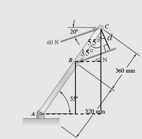
Chapter 3.3, Problem 49P
Two parallel 60-N forces are applied to a lever as shown. Determine the moment of the couple formed by the two forces (a) by resolving each force into horizontal and vertical components and adding the moments of the two resulting couples, (b) by using the perpendicular distance between the two forces, (c) by summing the moments of the two forces about point A.
Expert Solution & Answer
Want to see the full answer?
Check out a sample textbook solution
Students have asked these similar questions
120 Rigid Bodies: Equivalent Systems of Forces
3.74 Two parallel 40-N forces are applied to a lever as shown. Deter-
mine the moment of the couple formed by the two forces (a) by
resolving each force into horizontal and vertical components and
adding the moments of the two resulting couples, (b) by using the
perpendicular distance between the two forces, (e) by summing the
moments of the two forces about point A.
20°
40 N
The tw hafts of a sneed-reducer unit are subiected to couples
mag d = 1 Ib I ad M
"couples with a gle quivalent couple, specifts mag-
.ade and the dire
40 N
270 mm
w It, respectiv y. Pplace
its axis.
55°
390 mm
A O
Fig. P3.74
1.
1. Which of the following gives the moment of the 100-N force about the x-axis?
2. Which of the following best valuates the equivalent force-couple set at A of the applied forces 50 N and 100 N? Note: F is the resultant force and C is the resultant couple.
3. Which of the following are the reactions at the support at A? R are force reactions and M are moment reactions.
Two parallel 40-N forces are applied to a lever as shown. Determine the moment of the couple formed by the two forces (a) by resolving each force into horizontal and vertical components and adding the moments of the two resulting couples, (b) by using the perpendicular distance between the two forces, (c) by summing the moments of the two forces about point A.
Chapter 3 Solutions
Statics and Mechanics of Materials
Ch. 3.1 - A 20-lb force is applied to the control rod AB as...Ch. 3.1 - A 20-lb force is applied to the control rod AB as...Ch. 3.1 - A 300-N force P is applied at point A of the bell...Ch. 3.1 - A 400-N force P is applied at point A of the bell...Ch. 3.1 - A 300-N force is applied at A as shown. Determine...Ch. 3.1 - A 300-N force is applied at A as shown. Determine...Ch. 3.1 - 3.7 and 3.8 The tailgate of a car is supported by...Ch. 3.1 - 3.7 and 3.8 The tailgate of a car is supported by...Ch. 3.1 - 3.9 and 3.10 It is known that the connecting rod...Ch. 3.1 - 3.9 and 3.10 It is known that the connecting rod...
Ch. 3.1 - Rod AB is held in place by the cord AC. Knowing...Ch. 3.1 - Prob. 12PCh. 3.1 - Determine the moment about the origin O of the...Ch. 3.1 - Determine the moment about the origin O of the...Ch. 3.1 - Prob. 15PCh. 3.1 - Prob. 16PCh. 3.1 - Prob. 17PCh. 3.1 - A wooden board AB, which is used as a temporary...Ch. 3.1 - Prob. 19PCh. 3.1 - A small boat hangs from two davits, one of which...Ch. 3.1 - Prob. 21PCh. 3.1 - In Prob. 3.16, determine the perpendicular...Ch. 3.1 - In Prob. 3.16, determine the perpendicular...Ch. 3.1 - In Prob. 3.20, determine the perpendicular...Ch. 3.2 - Given the vectors P=3i-j+2k,Q=4i+5j-3k, and...Ch. 3.2 - Prob. 26PCh. 3.2 - Knowing that the tension in cable AC is 1260 N,...Ch. 3.2 - Knowing that the tension in cable AD is 405 N,...Ch. 3.2 - Three cables are used to support a container as...Ch. 3.2 - Three cables are used to support a container as...Ch. 3.2 - The 20-in. tube AB can slide along a horizontal...Ch. 3.2 - Solve Prob. 3.31 for the position corresponding to...Ch. 3.2 - Prob. 33PCh. 3.2 - Prob. 34PCh. 3.2 - Knowing that the tension in cable AB is 570 N,...Ch. 3.2 - Prob. 36PCh. 3.2 - A farmer uses cables and winch pullers B and E to...Ch. 3.2 - Solve Prob. 3.37 when the tension in cable AB is...Ch. 3.2 - To lift a heavy crate, a man uses a block and...Ch. 3.2 - Prob. 40PCh. 3.2 - Prob. 41PCh. 3.2 - Prob. 42PCh. 3.2 - Prob. 43PCh. 3.2 - A sign erected on uneven ground is guyed by cables...Ch. 3.2 - The frame ACD is hinged at and D and is supported...Ch. 3.2 - In Prob. 3.45, determine the moment about the...Ch. 3.2 - Prob. 47PCh. 3.2 - Prob. 48PCh. 3.3 - Two parallel 60-N forces are applied to a lever as...Ch. 3.3 - A plate in the shape of a parallelogram is acted...Ch. 3.3 - Prob. 51PCh. 3.3 - Prob. 52PCh. 3.3 - Four 112-in. -diameter pegs are attached to a...Ch. 3.3 - Prob. 54PCh. 3.3 - Prob. 55PCh. 3.3 - Prob. 56PCh. 3.3 - Replace the two couples shown with a single...Ch. 3.3 - Prob. 58PCh. 3.3 - Shafts A and B connect the gear box to the wheel...Ch. 3.3 - Prob. 60PCh. 3.3 - Prob. 61PCh. 3.3 - The force P has a magnitude of 250 N and is...Ch. 3.3 - Prob. 63PCh. 3.3 - A 260-lb force is applied at A to the rolled-steel...Ch. 3.3 - Prob. 65PCh. 3.3 - A force and couple act as shown on a square plate...Ch. 3.3 - Prob. 67PCh. 3.3 - Prob. 68PCh. 3.3 - Prob. 69PCh. 3.3 - Replace the 150-N force by an equivalent...Ch. 3.3 - Prob. 71PCh. 3.3 - Prob. 72PCh. 3.4 - A 4-m-long beam is subjected to a variety of...Ch. 3.4 - Prob. 74PCh. 3.4 - Determine the single equivalent force and the...Ch. 3.4 - The weights of two children sitting at ends A and...Ch. 3.4 - Prob. 77PCh. 3.4 - Prob. 78PCh. 3.4 - Four forces act on a 700375 -mm plate as shown....Ch. 3.4 - Prob. 80PCh. 3.4 - Prob. 81PCh. 3.4 - A truss supports the loading shown. Determine the...Ch. 3.4 - A machine component is subjected to the forces and...Ch. 3.4 - Solve Prob. 3.83, assuming that P=60N.Ch. 3.4 - Prob. 85PCh. 3.4 - Prob. 86PCh. 3.4 - Prob. 87PCh. 3.4 - Prob. 88PCh. 3.4 - Prob. 89PCh. 3.4 - Assuming e 600 in Prob. 3.89, replace the two...Ch. 3.4 - A blade held in a brace is used to tighten a screw...Ch. 3.4 - Prob. 92PCh. 3.4 - Four signs are mounted on a frame spanning a...Ch. 3.4 - Prob. 94PCh. 3.4 - Prob. 95PCh. 3.4 - Three children are standing on a 55-m raft. The...Ch. 3 - For the shift lever shown, determine the magnitude...Ch. 3 - Consider the volleyball net shown. Determine the...Ch. 3 - A crane is oriented so that the end of the 25-m...Ch. 3 - The 25-m crane boom AO lies in the yz plane....Ch. 3 - A single force P acts at C in a direction...Ch. 3 - While tapping a hole, a machinist applies the...Ch. 3 - A 500-N force is applied to a bent plate as shown....Ch. 3 - Prob. 104RPCh. 3 - Prob. 105RPCh. 3 - Prob. 106RPCh. 3 - Prob. 107RPCh. 3 - A regular tetrahedron has six edges of length a. A...
Additional Engineering Textbook Solutions
Find more solutions based on key concepts
The triple jump is a track-and-field event in which an athlete gets a running start and tries to leap as far as...
Vector Mechanics For Engineers
6–1C A mechanic claims to have developed a car engine that runs on water instead of gasoline. What is your resp...
Thermodynamics: An Engineering Approach
5.1 through 5.9
Locate the centroid of the plane area shown.
Fig. P5.1
Vector Mechanics for Engineers: Statics and Dynamics
How is the hydrodynamic entry length defined for flow in a pipe? Is the entry length longer in laminar or turbu...
Fluid Mechanics Fundamentals And Applications
A nozzle at A discharges water with an initial velocity of 36 ft/s at an angle with the horizontal. Determine ...
Vector Mechanics for Engineers: Dynamics
Three rigid bodies, 2,3, and 4, are connected by four springs as shown in the figure. A horizontal force of 1,0...
Introduction To Finite Element Analysis And Design
Knowledge Booster


Learn more about
Need a deep-dive on the concept behind this application? Look no further. Learn more about this topic, mechanical-engineering and related others by exploring similar questions and additional content below.Similar questions
- Knowing that the resultant of the two forces is vertical, determine the anglearrow_forwardThe two forces of magnitude F=30kN form a couple. Determine the corresponding couple-vector.arrow_forwardGiven that T=43kN and W=38kN, determine the magnitude and sense of the moments about point B of the following: (a) the force T; (b) the force W; and (c) forces T and W combined.arrow_forward
- (a) Determine the moment of force F about point C.(b) Determine the perpendicular distance (d) between point C and the line of action of force F.arrow_forwardForce P and couple M are applied at A as shown. 1. Suppose an equivalent system was made such that only force at B and a couple are present. What gives the magnitude of force at B and the couple in the equivalent system? 2. If the force P and couple M is to be replaced with a single force, where is the point of application of this single force along bar ABCD in order to have the same external effect as the original set of force P and couple M? (How many m to the left or right of B)arrow_forwardA couple M and the three forces shown are applied to an angle bracket. Find the moment of the couple if the line of action of the resultant of the force system is to pass through ( a) point A , (b) point , (c) point C.arrow_forward
- The overhead electric hoist C rides along a track on the horizontal beam AB. In addition to the 500-KN vertical force carried by the hoist, the beam also supports the three vertical forces shown. (a) If x=5m determine the resultant of the four forces carried by the beam. (b) Determine the distance x for which the resultant of the four forces would act at the center of the span AB.arrow_forwardA couple M and the three forces are applied to an angle bracket. Find the moment of the couple if the line ofaction of the resultant of the force system is to pass through (a) point A, (b) point B, and (c) point C.arrow_forward1. Given the two forces and a couple M₁ shown, find the equivalent force-couple system acting at O. Then, replace the force-couple system with a wrench resultant, by writing the force and the moment associated with the wrench in a Cartesian vector form. You can assume that the point P through which the line of action of the wrench passes is already known and do not need to be calculated. M₁ 7m = 100 N·m 3 m 3 m 400 N 3 m SOTER 600 Narrow_forward
- Two 80-N forces are applied as shown to the corners B and D of a rectangular plate. (a) Determine the moment of the couple formed by the two forces by resolving each force into horizontal and vertical components and adding the moments of the two resulting couples. (b) Use the result obtained to determine the perpendicular distance between lines BE and DF.arrow_forwardtwo parallel 60 N forces are applied as shown to the corners A and C of a 200 mm square plate. Determine the moment of the couple formed by the two forces (a) by multiplying their magnitude by their perpendicular distance , (b) by resolving each force into horizontal and vertical components and adding the moments of the two result ing couples. please give the solutionarrow_forwarda. Replace the force system with a resultant force and couple moment about the Origin O. b. Replace the force system with a resultant force and couple moment about the Point B.arrow_forward
arrow_back_ios
SEE MORE QUESTIONS
arrow_forward_ios
Recommended textbooks for you
 International Edition---engineering Mechanics: St...Mechanical EngineeringISBN:9781305501607Author:Andrew Pytel And Jaan KiusalaasPublisher:CENGAGE L
International Edition---engineering Mechanics: St...
Mechanical Engineering
ISBN:9781305501607
Author:Andrew Pytel And Jaan Kiusalaas
Publisher:CENGAGE L
Introduction To Engg Mechanics - Newton's Laws of motion - Kinetics - Kinematics; Author: EzEd Channel;https://www.youtube.com/watch?v=ksmsp9OzAsI;License: Standard YouTube License, CC-BY