Statics and Mechanics of Materials
2nd Edition
ISBN: 9780073398167
Author: Ferdinand P. Beer, E. Russell Johnston Jr., John T. DeWolf, David Mazurek
Publisher: McGraw-Hill Education
expand_more
expand_more
format_list_bulleted
Concept explainers
Videos
Textbook Question
Chapter 3.4, Problem 73P
A 4-m-long beam is subjected to a variety of loadings. (a) Replace each loading with an equivalent force-couple system at end A of the beam. (b) Which of the loadings are equivalent?
Expert Solution & Answer
Want to see the full answer?
Check out a sample textbook solution
Students have asked these similar questions
Replace the loading system acts on beam shown in Fig. (3) by
an equivalent system consists (Single Force & Couple at point A).
40 N
A
30 N
B
200 N·m
50 N
PROBLEM 3.101
A 4-m-long beam is subjected to a variety of loadings. (a) Replace each loading with an equivalent force-
couple system at end A of the beam. (b) Which of the loadings are equivalent?
400 N
200 Nm
400 N
200 N
200 N
800 N
1800 N-m
2300 Nm
800 N
200 N-m
2400 N-m
4000 N-m
600 N
400 N
300 N
3
(A)
900 N-m
200 N
400 N-m
300 N
300 N-m
300 N
300 N·m
800 N
900 N
4500 N-m
300 N-m
200 N
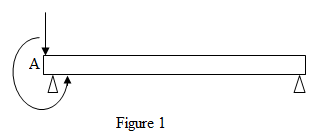
Q3/ Replace the loading system acts on beam shown in Fig. (3) by
an equivalent system consists (Single Force & Couple at point A).
Fig. (1)
40 N
30 N
B
3m
Fig. (3)
200 Nm
50 N
Chapter 3 Solutions
Statics and Mechanics of Materials
Ch. 3.1 - A 20-lb force is applied to the control rod AB as...Ch. 3.1 - A 20-lb force is applied to the control rod AB as...Ch. 3.1 - A 300-N force P is applied at point A of the bell...Ch. 3.1 - A 400-N force P is applied at point A of the bell...Ch. 3.1 - A 300-N force is applied at A as shown. Determine...Ch. 3.1 - A 300-N force is applied at A as shown. Determine...Ch. 3.1 - 3.7 and 3.8 The tailgate of a car is supported by...Ch. 3.1 - 3.7 and 3.8 The tailgate of a car is supported by...Ch. 3.1 - 3.9 and 3.10 It is known that the connecting rod...Ch. 3.1 - 3.9 and 3.10 It is known that the connecting rod...
Ch. 3.1 - Rod AB is held in place by the cord AC. Knowing...Ch. 3.1 - Prob. 12PCh. 3.1 - Determine the moment about the origin O of the...Ch. 3.1 - Determine the moment about the origin O of the...Ch. 3.1 - Prob. 15PCh. 3.1 - Prob. 16PCh. 3.1 - Prob. 17PCh. 3.1 - A wooden board AB, which is used as a temporary...Ch. 3.1 - Prob. 19PCh. 3.1 - A small boat hangs from two davits, one of which...Ch. 3.1 - Prob. 21PCh. 3.1 - In Prob. 3.16, determine the perpendicular...Ch. 3.1 - In Prob. 3.16, determine the perpendicular...Ch. 3.1 - In Prob. 3.20, determine the perpendicular...Ch. 3.2 - Given the vectors P=3i-j+2k,Q=4i+5j-3k, and...Ch. 3.2 - Prob. 26PCh. 3.2 - Knowing that the tension in cable AC is 1260 N,...Ch. 3.2 - Knowing that the tension in cable AD is 405 N,...Ch. 3.2 - Three cables are used to support a container as...Ch. 3.2 - Three cables are used to support a container as...Ch. 3.2 - The 20-in. tube AB can slide along a horizontal...Ch. 3.2 - Solve Prob. 3.31 for the position corresponding to...Ch. 3.2 - Prob. 33PCh. 3.2 - Prob. 34PCh. 3.2 - Knowing that the tension in cable AB is 570 N,...Ch. 3.2 - Prob. 36PCh. 3.2 - A farmer uses cables and winch pullers B and E to...Ch. 3.2 - Solve Prob. 3.37 when the tension in cable AB is...Ch. 3.2 - To lift a heavy crate, a man uses a block and...Ch. 3.2 - Prob. 40PCh. 3.2 - Prob. 41PCh. 3.2 - Prob. 42PCh. 3.2 - Prob. 43PCh. 3.2 - A sign erected on uneven ground is guyed by cables...Ch. 3.2 - The frame ACD is hinged at and D and is supported...Ch. 3.2 - In Prob. 3.45, determine the moment about the...Ch. 3.2 - Prob. 47PCh. 3.2 - Prob. 48PCh. 3.3 - Two parallel 60-N forces are applied to a lever as...Ch. 3.3 - A plate in the shape of a parallelogram is acted...Ch. 3.3 - Prob. 51PCh. 3.3 - Prob. 52PCh. 3.3 - Four 112-in. -diameter pegs are attached to a...Ch. 3.3 - Prob. 54PCh. 3.3 - Prob. 55PCh. 3.3 - Prob. 56PCh. 3.3 - Replace the two couples shown with a single...Ch. 3.3 - Prob. 58PCh. 3.3 - Shafts A and B connect the gear box to the wheel...Ch. 3.3 - Prob. 60PCh. 3.3 - Prob. 61PCh. 3.3 - The force P has a magnitude of 250 N and is...Ch. 3.3 - Prob. 63PCh. 3.3 - A 260-lb force is applied at A to the rolled-steel...Ch. 3.3 - Prob. 65PCh. 3.3 - A force and couple act as shown on a square plate...Ch. 3.3 - Prob. 67PCh. 3.3 - Prob. 68PCh. 3.3 - Prob. 69PCh. 3.3 - Replace the 150-N force by an equivalent...Ch. 3.3 - Prob. 71PCh. 3.3 - Prob. 72PCh. 3.4 - A 4-m-long beam is subjected to a variety of...Ch. 3.4 - Prob. 74PCh. 3.4 - Determine the single equivalent force and the...Ch. 3.4 - The weights of two children sitting at ends A and...Ch. 3.4 - Prob. 77PCh. 3.4 - Prob. 78PCh. 3.4 - Four forces act on a 700375 -mm plate as shown....Ch. 3.4 - Prob. 80PCh. 3.4 - Prob. 81PCh. 3.4 - A truss supports the loading shown. Determine the...Ch. 3.4 - A machine component is subjected to the forces and...Ch. 3.4 - Solve Prob. 3.83, assuming that P=60N.Ch. 3.4 - Prob. 85PCh. 3.4 - Prob. 86PCh. 3.4 - Prob. 87PCh. 3.4 - Prob. 88PCh. 3.4 - Prob. 89PCh. 3.4 - Assuming e 600 in Prob. 3.89, replace the two...Ch. 3.4 - A blade held in a brace is used to tighten a screw...Ch. 3.4 - Prob. 92PCh. 3.4 - Four signs are mounted on a frame spanning a...Ch. 3.4 - Prob. 94PCh. 3.4 - Prob. 95PCh. 3.4 - Three children are standing on a 55-m raft. The...Ch. 3 - For the shift lever shown, determine the magnitude...Ch. 3 - Consider the volleyball net shown. Determine the...Ch. 3 - A crane is oriented so that the end of the 25-m...Ch. 3 - The 25-m crane boom AO lies in the yz plane....Ch. 3 - A single force P acts at C in a direction...Ch. 3 - While tapping a hole, a machinist applies the...Ch. 3 - A 500-N force is applied to a bent plate as shown....Ch. 3 - Prob. 104RPCh. 3 - Prob. 105RPCh. 3 - Prob. 106RPCh. 3 - Prob. 107RPCh. 3 - A regular tetrahedron has six edges of length a. A...
Knowledge Booster


Learn more about
Need a deep-dive on the concept behind this application? Look no further. Learn more about this topic, mechanical-engineering and related others by exploring similar questions and additional content below.Similar questions
- Q3/ Shown in fig.( 3 ) replace the loading system by an equivalent resultant force and couple moment acting at point A. 900 N\30° 300 N 300 N-m 0.75 m 0.75 m 0.75 m 0.75 m Fig.( 3 )arrow_forwardProblem 2: Determine the internal normal force (P), shear force (V), and moment acting in the beam at point B, which is located just to the left of the 800-lb force. 800 lb 400 lb 300 lb-ft B -6 ft -3 ft-3 ft---2 ft-arrow_forwardReplace the loading system acts on beam shown in Fig. (3) by an equivalent system consists (Single Force & Couple at point A). 40 N 30 N 3m 200 Nom 50 Narrow_forward
- Draw the shearing-force and bending-moment diagrams for the following beams: 1. A cantilever of length 20 m carrying a load of 10 kN at a distance of 15 m from the supported end. 2. A cantilever of length 20 m carrying a load of 10 kN is uniformly distributed over the inner 15 m of its length. 3. A cantilever of length 12 m carrying a load of 8 kN, applied 5 m from the supported end, and a load of 2kNlm over its whole length.arrow_forwardTwo live loads of 7 KN and 9 KN separated 5 m apart, are to cross a simple beam. Also, a uniform live load of 6 KN/m, 6 m long, is expected to cross the same beam. The simple supports are marked A and B and a point C is located 4 m from A. Determine: (a) the maximum moment at C due to the two concentrated live loads if the length of the beam is (a.1) 8.4 m; (a.2) 10 m. (b) The maximum moment at C due to the uniform live load if the length of the beam is (b.1) 8.4 m; (b.2) 10 m. (c) The maximum moment in the beam due to the combined effects of the two concentrated live loads and the uniform live loads if the length of the beam is (c.1) 8.4 m; (c.2) 10 m. part (c), I am asking for the ABSOLUTE maximum moment in the beam due to the combined effects of the two live loads and the uniform live load. Please be guided and informed accordingly. Good luck!arrow_forwardDetermine the: (A) reaction forces at both ends when the distributed load uniform and has a magnitude of 5 kN/m. (B) internal forces and moment at A for the uniformly distributed loading.arrow_forward
- (b) The gudgeon pin is used to connect the piston and the connecting rod. Show from first principles that the maximum bending moment acting on the gudgeon pin is given by: PL M = 8 where P is the maximum gas load and L is the length of the pinarrow_forwardQ3/ Replace the loading system acts on beam shown in Fig. (3) by an equivalent system consists (Single Force & Couple at point A). 3m 30 N Fig. (3) 200 N-marrow_forwardProblem 3: Given the cantilever beam show, determine the value of forces N and O if the resultant of the forces will be a downward force of 450N, 9 meters from the right end of the bar. 150N 300N 4in Com 4marrow_forward
- Question 14. 650 N 500 N 30° 300 N 1500 N · m 60° B -31 -5 m- Replace the loading system acting on the post by an equivalent resultant force and couple moment at point A.arrow_forwardQ2 :The railway wheel exerts a force on the rail and through the wooden beam, and the gravel can be assumed as a reaction over the length of the wooden beam, as shown in Fig. Q2. (a) Draw the shear force and bending moment diagrams for the beam and determine the magnitude of the maximum load w per kN/m. (b) If the allowable bending stress is 10 MN/m² and the aspect ratio of the rectangular wood beam is h/b = 0.5, determine the minimum width b and height h that can be used for the beam. 60 kN Į 45 cm 60 KN Uniform Reaction w kN/m 150 cm 45 cm Fig. Q2 Railway Loadingarrow_forwardReplace the loading system acts on beam shown in Fig. (3) by an equivalent system consists (Single Force & Couple at point A). Fig. (1) 40 N 30 N Fig. (3) 200 N-m 50 Narrow_forward
arrow_back_ios
SEE MORE QUESTIONS
arrow_forward_ios
Recommended textbooks for you
 Elements Of ElectromagneticsMechanical EngineeringISBN:9780190698614Author:Sadiku, Matthew N. O.Publisher:Oxford University Press
 Mechanics of Materials (10th Edition)Mechanical EngineeringISBN:9780134319650Author:Russell C. HibbelerPublisher:PEARSON
 Thermodynamics: An Engineering ApproachMechanical EngineeringISBN:9781259822674Author:Yunus A. Cengel Dr., Michael A. BolesPublisher:McGraw-Hill Education
 Control Systems EngineeringMechanical EngineeringISBN:9781118170519Author:Norman S. NisePublisher:WILEY
 Mechanics of Materials (MindTap Course List)Mechanical EngineeringISBN:9781337093347Author:Barry J. Goodno, James M. GerePublisher:Cengage Learning
 Engineering Mechanics: StaticsMechanical EngineeringISBN:9781118807330Author:James L. Meriam, L. G. Kraige, J. N. BoltonPublisher:WILEY
Elements Of Electromagnetics
Mechanical Engineering
ISBN:9780190698614
Author:Sadiku, Matthew N. O.
Publisher:Oxford University Press
Mechanics of Materials (10th Edition)
Mechanical Engineering
ISBN:9780134319650
Author:Russell C. Hibbeler
Publisher:PEARSON
Thermodynamics: An Engineering Approach
Mechanical Engineering
ISBN:9781259822674
Author:Yunus A. Cengel Dr., Michael A. Boles
Publisher:McGraw-Hill Education
Control Systems Engineering
Mechanical Engineering
ISBN:9781118170519
Author:Norman S. Nise
Publisher:WILEY
Mechanics of Materials (MindTap Course List)
Mechanical Engineering
ISBN:9781337093347
Author:Barry J. Goodno, James M. Gere
Publisher:Cengage Learning
Engineering Mechanics: Statics
Mechanical Engineering
ISBN:9781118807330
Author:James L. Meriam, L. G. Kraige, J. N. Bolton
Publisher:WILEY
Types Of loads - Engineering Mechanics | Abhishek Explained; Author: Prime Course;https://www.youtube.com/watch?v=4JVoL9wb5yM;License: Standard YouTube License, CC-BY