
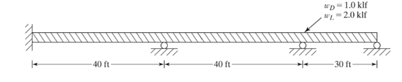
To Select: The lightest section for the continuous beam in the figure using the LFRD method, use elastic method, and factored loads and
Answer to Problem 10.1PFS
Explanation of Solution
Given:
The continuous beam is shown below.
And steel is
Calculation:
Compute the factored acting on the beam using the equation.
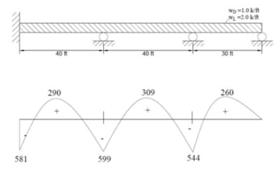
Draw the bending moment diagram with maximum and minimum values.
Using
Calculate the maximum factored positive moment of the beam.
Select a W-section from table 3.2 of the AISC Manual such that.
Since,
Therefore, use
Want to see more full solutions like this?
Chapter 10 Solutions
Structural Steel Design (6th Edition)

- Use NSCP 2015. The beam shown has continuous lateral support of both flanges. The uniform load consisting of 50% dead load and 50% live load. The dead load includes the weight of the beam. Used grade 50 steel. 6 k/ft |--0-0²- -18'-0"- fo 4-6- -6'-0" 1. Considering LRFD. Which of the following most nearly gives the design load Wu? 2. Considering LRFD. Which of the following most nearly gives the maximum negative design moment, Mu in ft-kips? 3. Considering W12x35 beam section, The section is 4. Considering ASD the W12x35 beam section, Which of the following most nearly gives allowable strength in ft-kipsarrow_forwardTutorial 7 Вeams 1. A simply supported beam must carry the factored ultimate loads (two 15kN point loads) shown in the figure. Do not consider the self-weight of the beam. The beam is laterally and torsional supported only at A, B, C and D. For a 203 x 133 x 25 I- section: (Grade 350 W steel) (a) Determine the class of the section. (b) Determine whether the section has sufficient flexural resistance. 15 kN 15 kN 4,0 m 2,0 m 4,0 marrow_forwardQ2) The members of the truss structure shown below is plain concrete. The compressive strength of the concrete is 25 MPa. Compute the maximum load P that can be carried by the structure. (Cross section of each member of the truss is 200 x 200 mm and don't use material factors and do not consider slenderness) Comment on your results briefly. P A& 2m SC 2 m 1380 2m Darrow_forward
- Plate Girder Solve the following Problem For the plate girder shown, consider shear only, check the adequacy of the girder and determine the required spacing of transverse stiffeners if needed. Take Fy 36 ksi. Use ASD method. 300 k 16" 1/4" 48" 20 20arrow_forwardThe given girder has beams framing into it at the ends and at every L/3 point. The beam carries a service live load of 20 kips as shown and superimposed uniformly distributed service dead load of 10 kip/ft. Select the lightest A992 W-section that can carry the load. Do not check for deflection. P, = 20 kips LL PLL W. = 10 kip/ft DL = 20 ft WDL L/3 BEAMS FRAMING INTO GIRDER Larrow_forwardA W 16 x50 is used as a beans to carry a uniform we and dead load including own weight of 35.7 kN/m and an axial tension load of T acting through the centroid, of the member. It has a simple span of 5.9 m. The compression flange of the member is laterally supported against local buckling.Use A 36 steel, Fy = 248 MPa. Properties of W 16 x 50A= 9483.85 mm^2d= 412.75 mmbf= 179.65 mmtf= 15.95 mmtw= 9.65 mmSx= 1324 x 10^3 mm^3Sy = 172 × 10^3 mm^3 Questions:Determine the Safe axial load T that the beam could carry.Hint Answer: 399.65KNarrow_forward
- Verify the bending resistance and global stability of the beam. Gravity load is 0.9kN/m, concentrated load 100 kN is applied in the midpoint of the span. Q235 steel is used. a. No brace in the middle of the span. Concentrated load is applied on the top flange. b. No brace in the middle of the span. Concentrated load is applied on the bottom flange. (optional) C. Braced in the middle of the span. Concentrated load is applied on the top flange. d. Same as (a), use Q345B steel. 0.9kN/m 200×12 5000 100KN 5000 I 776x8 200×12arrow_forwardQ3) A simply supported beam has been satisfactorily designed to resist flexure. At a distance d from the support face the following condition exist: V-45 KN, M-9KN.m V₁-25KN,M₁-18KN.m h=500mm, d=450mm, b=300mm, f'c-21MPa and fy=350MPa.As consists of 3 No.29 bars. A/ Check the beam for shear requirements. use: V - (0.16 [Fe + 170. Xd) b. d fe Pw M₂arrow_forwardDetermine whether a W24 x 117 of A992 steel is adequate for the beam shown. The uniform load does not include the weight of the beam. Lateral support is provided at A, B, and C. Use LRFD. P= 12 k P = 36 k WD = 1 k/ft WL = 3 k/ft 10 20- 30arrow_forward
- Verify the adequacy of column AB, part of a sway frame structure, to carry the loads shown in the figure. The column is made of ASTM A36 steel (Fy = 250 MPa). Use ASD specifications. For determining its effective length factor, neglect inelastic effect. %3D W21X62 C W21X62 L=5 m L=5 m Flanges of Columns and web of girders are in the plane of the frame NOTE: Take note of the moment of inertia to be used (ly) for columns. W18X50 W18X50 L=5 m L=5 m P(DL) = 40 kN NM 001 = (10)d NM 00S = (1)d NY SZI = (1)d W21X62 L-4.2m W21X62 L=4.2 marrow_forwardCurrent Attempt in Progress A pin-connected structure is supported and loaded as shown. Member ABCD is rigid and is horizontal before the load Pis applied. Bars (1) and (2) are both made from steel (E - 30600 ksi) and both have a cross-sectional area of 0.87 in.?. Assume L;-87 in, Lg-111 in., a-50 in., b-93 in, and c-39 in. If the normal stress in each steel bar must be limited to 19.4 ksi, determine the maximum load Pthat may be applied to the rigid bar. (2) (1) D Answer: P- kips.arrow_forwardUse LFRD for Probs. except as indicated. Use both methods for all others. Considering moment only and assuming full lateral support for the compression flanges, select the lightest sections available, using 50 ksi steel and the LRFD method. The loads shown include the effect of the beam self-weights. Use elastic analysis factored loads and the 0.9 rule. FIGURE 10-5 D-05klf 2klf 15 ft- 40 tarrow_forward
 Steel Design (Activate Learning with these NEW ti...Civil EngineeringISBN:9781337094740Author:Segui, William T.Publisher:Cengage Learning