
Concept explainers
Videos
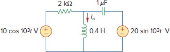
Use mesh analysis to find current io in the circuit of Fig. 10.74.
Figure 10.74
For Prob. 10.26.
Find the current
Answer to Problem 26P
The value of current
Explanation of Solution
Formula used:
Write the expression to calculate impedance of the inductor.
Here,
Write the expression to calculate impedance of the capacitor.
Here,
Write the general representation of sinusoidal function.
Here,
Write the general expression to phasor transform of sinusoidal function from time domain to frequency domain.
Here,
Write the polar form representation of frequency domain.
Calculation:
Comparing given source voltage
Substitute
Convert
Substitute
Substitute
The frequency domain representation of given figure with the assumed current direction is shown in Figure 1.
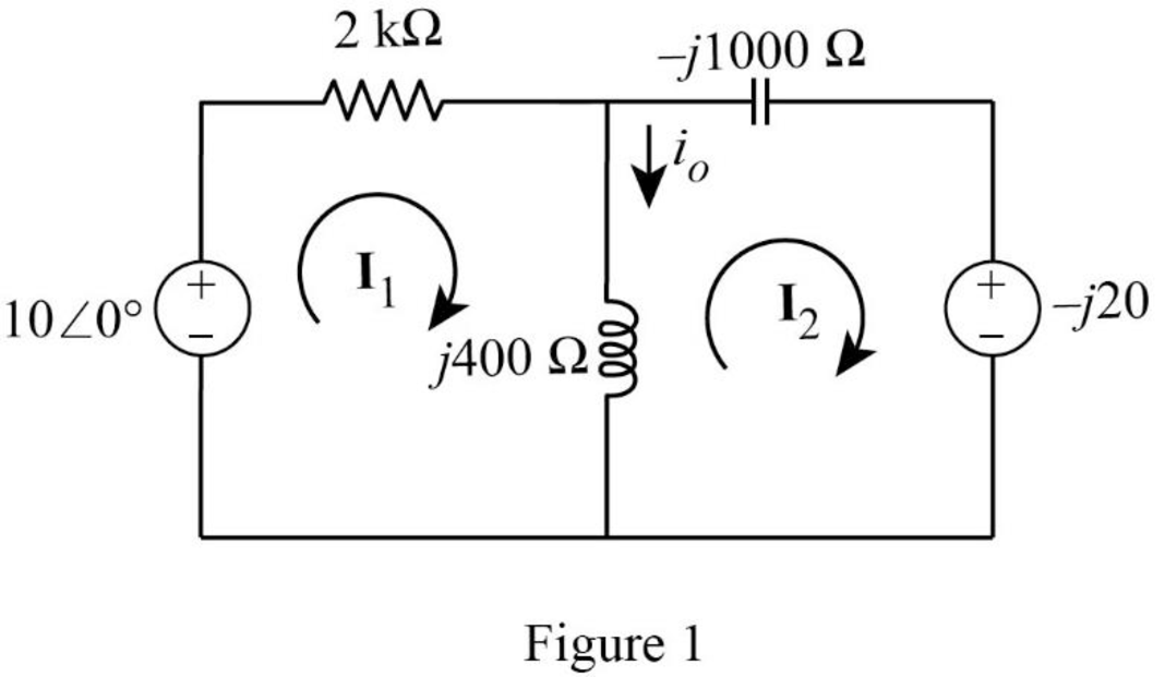
Apply Kirchhoff’s voltage law to the loop with current
Apply Kirchhoff’s voltage law to the loop with current
Represent equation (5) and (6) in matrix form.
Obtain the value of determinants as follows.
Write the expression for mesh currents using Cramer’s rule.
Substitute
Substitute
From Figure 1, write the expression for current
Substitute
Represent the current in time domain.
Conclusion:
Therefore, the value of current
Want to see more full solutions like this?
Chapter 10 Solutions
Fundamentals of Electric Circuits


- Calculate the output voltage, V o , in the circuit of Fig. 10.73 .arrow_forwardDetermine the Thevenin equivalent of the circuit in Fig. 10.27 as seen from the terminals a-b.arrow_forward2 If Is-60mA, nd all unknown currents e 10:39 Electrical Circuit Analysis Lab. 2.5 N 102 25 2 150 30 2arrow_forward
- 4. What is the range of the voltage-gain adjustment in the circuit of Fig. 10.63? S00 ka 10 ka 10 ka V.arrow_forwardfind current I° in the circuit of Fig. 10.8 using the superposition theorem.arrow_forward10.42: The following DC measurements were made on the resistive network: Measurement 1 V-1mV Measurement 2 V=20mV =20µA 6.25mV voltage source with 3002 resistor is applied to port 1 and a variable resistor Ro is connected across port 2 and adjusted for maximum power transfer to Ro. Find the maximum power? V-10V V-40V L=200LAarrow_forward
- For the circuit shown in Fig. 10.107, find the Norton equivalent circuit at terminals a-b. 60 Q 40 Q 3/60° A o a bo j80 N -j30 Q llarrow_forwardFind vo of the circuit of Fig. 10.13 using the superposition theorem. 2 H 1Ω 4Ω ww ll 2 sin 5t A 0.1 F 5 V 10 cos 2t Varrow_forwardCalculate current I, in the circuit of Fig. 10.11. Answer: 2.538/5.943° A. Practice Problem 10.4 1012 www -j4Q j8Q2 25/0° V 592 -1692 Figure 10.11 For Practice Prob. 10.4. 1/0° Aarrow_forward
- Find lo in the circuit of Fig. 10.19 using the concept of source transformation. 2Ω j1Ω wwm 4Ω 8/90° A j5 Q 1Ω -j3 Q -j2 N wwarrow_forwardDetermine the Norton equivalent of the circuit in Fig. 10.30 as seen from terminals a-b. Use the equivalent to find I ww IA -130 wwH ww 10A 10/0 V O 290 Aarrow_forwardCalculate V, in the circuit of Fig. 10.17 using the method of source transformation. 5Ω -j13 2 ww ww 3 2 20-90° V 10 Ω j4 2 wwarrow_forward
 Introductory Circuit Analysis (13th Edition)Electrical EngineeringISBN:9780133923605Author:Robert L. BoylestadPublisher:PEARSON
 Delmar's Standard Textbook Of ElectricityElectrical EngineeringISBN:9781337900348Author:Stephen L. HermanPublisher:Cengage Learning
 Programmable Logic ControllersElectrical EngineeringISBN:9780073373843Author:Frank D. PetruzellaPublisher:McGraw-Hill Education
 Fundamentals of Electric CircuitsElectrical EngineeringISBN:9780078028229Author:Charles K Alexander, Matthew SadikuPublisher:McGraw-Hill Education
 Electric Circuits. (11th Edition)Electrical EngineeringISBN:9780134746968Author:James W. Nilsson, Susan RiedelPublisher:PEARSON
 Engineering ElectromagneticsElectrical EngineeringISBN:9780078028151Author:Hayt, William H. (william Hart), Jr, BUCK, John A.Publisher:Mcgraw-hill Education,