
Concept explainers
Videos
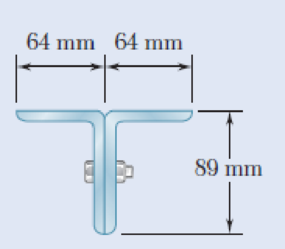
Two 89 × 64-mm angles are bolted together as shown for use as a column of 2.4-m effective length to carry a centric load of 325 kN. Knowing that the angles available have thicknesses of 6.4 mm, 9.5 mm, and 12.7 mm, use allowable stress design to determine the lightest angles that can be used. Use σY = 250 MPa and E = 200 GPa.
Fig. P10.84
Find the lightest angles that can be used.
Answer to Problem 84P
The lightest angle that can be used for the design is
Explanation of Solution
Given information:
The effective length of the column is
The allowable yield strength of the steel is
The modulus of elasticity of the steel is
The centric load acting in the column is
Calculation:
Consider the thickness of the angle section as 9.5 mm.
Refer to Appendix C “Properties of Rolled-Steel Shapes” in the textbook.
For
The cross sectional area of the angle (A) is
The moment of inertia in x-axis is
The moment of inertia in y-axis is
The centroid distance from the flange in x-axis is
The area of the two angle section is
The moment of inertia in x-axis is
Find the moment of inertia in y-axis using the relation.
Substitute
The minimum moment of inertia is
Find the minimum radius of gyration (r) using the relation.
Substitute
Find the slenderness ratio
Here, the modulus of elasticity of the material is E and the allowable yield strength is
Substitute 200 GPa for E and 250 MPa for
Find the ratio of effective length
Find the effective stress
Substitute 200 GPa for E and 97.22 for
Find the critical stress
Substitute 250 MPa for
Calculate the allowable stress
Substitute 151.472 MPa for
Calculate the allowable load
Substitute 90.702 MPa for
The centric load is greater than the allowable load. Hence, the design is unsafe.
Consider the thickness of the angle section as 12.7 mm.
Refer to Appendix C “Properties of Rolled-Steel Shapes” in the textbook.
For
The cross sectional area of the angle (A) is
The moment of inertia in x-axis is
The moment of inertia in y-axis is
The centroid distance from the flange in x-axis is
The area of the two angle section is
The moment of inertia in x-axis is
Find the moment of inertia in y-axis using the relation.
Substitute
The minimum moment of inertia is
Find the minimum radius of gyration (r) using the relation.
Substitute
Find the slenderness ratio
Here, the modulus of elasticity of the material is E and the allowable yield strength is
Substitute 200 GPa for E and 250 MPa for
Find the ratio of effective length
Find the effective stress
Substitute 200 GPa for E and 95.12 for
Find the critical stress
Substitute 250 MPa for
Calculate the allowable stress
Substitute 154.753 MPa for
Calculate the allowable load
Substitute 92.667 MPa for
The centric load is less than the allowable load. Hence, the design is unsafe.
Therefore, the lightest angle that can be used for the design is
Want to see more full solutions like this?
Chapter 10 Solutions
Mechanics of Materials, 7th Edition


- PROBLEM 1 Determine the allowable weight that the assembly can handle if the cable AB has a working stress of 200 Mpa and cable AC has a working stress of 150 Mpa. The cable cross sectional areas are 300 mm? for cable AB and 330 mm2 for cable AC. B 50° 28° A Warrow_forwardIn the steel structure shown, a 6-mm-diameter pin is used at C and 12-mm-diameter pins are used at B and D. The ultimate shearing stress is 150 MPa at all connections, and the ultimate normal stress is 350 MPa in link BD. Knowing that a factor of safety of 3.0 is desired, determine the largest load P that can be applied at A. Note that link BD is not reinforced around the pin holes. The largest load P that can be applied at A is kN.arrow_forwardA column with the cross section shown has a 13.5-ft effective length. Using a factor of safety equal to 3, determine the allowable centric load that can be applied to the column. Use E= 29 × 106 psi. (Round the final answer to one decimal place.) in.- 6 in. 10 in. in. in. The allowable centric load that can be applied to the column is kips.arrow_forward
- A steel column of 19-ft effective length must carry a centric load of 338 kips. Using Allowable Stress Design, select the wide-flange shape of 12-in. nominal depth that should be used. Use σY = 50 ksi and E = 29 × 106 psi. The wide-flange shape used is W12 × .arrow_forwardAn annular washer distributes the load P applied to a steel rod to a timber support. The rod's diameter is 22 mm, and the washer's inner diameter is 25 mm, which is larger than the hole's permissible outer diameter. Knowing that the axial normal stress in the steel rod is 35 MPa and the average bearing stress between the washer and the timber must not exceed 5 MPa, examine the smallest allowed outer diameter, d, of the washer. %3D %3D +22 mm P Figure 4arrow_forwardThe rigid beam BC is supported by rods (1) and (2). The cross-sectional area of rod (1) is 7 mm2. The cross-sectional area of rod (2) is 18 mm2. For a uniformly distributed load of w = 2.7 kN/m, determine the length a so that the normal stress is the same in each rod. Assume L = 5.65 m.arrow_forward
- а) An annular washer distributes the load P applied to a steel rod to a timber support. The rod's diameter is 22 mm, and the washer's inner diameter is 25 mm, which is larger than the hole's permissible outer diameter. Knowing that the axial normal stress in the steel rod is 35 MPa and the average bearing stress between the washer and the timber must not exceed 5 MPa, examine the smallest allowed outer diameter, d, of the washer. - 22 mm Figure 4arrow_forwardProblem 13.1 Two wooden members of 80mm x 120mm uniform rectangular cross section are joined by the simple glued scarf splice shown. The angle of the joint is ß = 30 degrees and the glued joint has a capacity of 410 kPa against tension stresses and 680 kPa against shear stresses. Determine the largest centric load P that can be applied. P 80 mm 120 mm Parrow_forwardThe steel frame shown has a diagonal brace BD with an area of 1548 sq.mm. Determine the largest allowable load P (in N) if the change in length of member BD is not to exceed 1.35 mm. Use x = 4.59m, y = 5.76m, and E = 199.3 Gpa. Express your answer in four decimal places.arrow_forward
- A steel plate 5/16 in. thick is embedded in a horizontal concrete slab and is used to anchor a high-strength vertical cable as shown. The diameter of the hole in the plate is 3/4in., the ultimate strength of the steel used is 36 ksi, and the ultimate bonding stress between plate and concrete is 300 psi. Knowing that a factor of safety of 3.60 is desired when P = 2.5 kips, determine (a) the required width a of the plate,(b) the minimum depth b to which a plate of that width should be embedded in the concrete slab. (Neglect the normal stresses betweenthe concrete and the lower end of the plate.)arrow_forwardThe steel tie bar shown is to be designed to carry a tension force of magnitudeP=120 kN when bolted between double brackets at A and B. The bar will be fabricated from 20-mm-thick plate stock. For the grade of steel tobe used, the maximum allowable stresses are σ =175 MPa, τ =100 MPa,and σb=350 MPa. Design the tie bar by determining the required values of(a) the diameter d of the bolt, (b) the dimension b at each end of the bar, and(c) the dimension h of the bar.arrow_forwardAn axial load P is supported by a short W8x40 column of cross-sectional area A=11.7 in? and is distributed to a concrete foundation by a square plate as shown. Knowing that the average normal stress in the column must not exceed 30ksi and that the bearing stress on the concrete foundation must not exceed 3.0 ksi, determine the side "a" of the plate that will provide the most economical and safe design.arrow_forward
 Elements Of ElectromagneticsMechanical EngineeringISBN:9780190698614Author:Sadiku, Matthew N. O.Publisher:Oxford University Press
 Mechanics of Materials (10th Edition)Mechanical EngineeringISBN:9780134319650Author:Russell C. HibbelerPublisher:PEARSON
 Thermodynamics: An Engineering ApproachMechanical EngineeringISBN:9781259822674Author:Yunus A. Cengel Dr., Michael A. BolesPublisher:McGraw-Hill Education
 Control Systems EngineeringMechanical EngineeringISBN:9781118170519Author:Norman S. NisePublisher:WILEY
 Mechanics of Materials (MindTap Course List)Mechanical EngineeringISBN:9781337093347Author:Barry J. Goodno, James M. GerePublisher:Cengage Learning
 Engineering Mechanics: StaticsMechanical EngineeringISBN:9781118807330Author:James L. Meriam, L. G. Kraige, J. N. BoltonPublisher:WILEY