
Whether a
Answer to Problem 11.1PFS
Satisfied
Explanation of Solution
Given:
Calculation:
The sectional properties are as follows:
Refer Table 3-2, “W shapes properties” in the AISC steel construction manual.
The ultimate load by LRFD is
The design moment is
Refer Table 1-1, “W shapes properties” in the AISC steel construction manual.
The available tensile strength is
The design strength is
Since,
The nominal moment strength is
Check:
The section is subjected to both the bending and axial tension:
Hence, it’s OK.
The ultimate load by ASD is
The design moment is
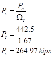
The design strength is
Since,
The nominal moment strength is
Check:
The section is subjected to both the bending and axial tension:
Hence, it’s OK.
Conclusion:
Therefore, the tension member
Want to see more full solutions like this?
Chapter 11 Solutions
Structural Steel Design (6th Edition)

- Answers: AB = kN E AH = kN Determine the force in each member of the loaded truss. All triangles are 3-4-5. Enter a the member is in tension, negative if in compression. BC - kN C 34kN kN BG E 34 kN BH - kN 15 kN BI = kN D B kN kN A E DE kN H G F DF = kN - 4 panels at 8 m- DG = kN DI kN EF = kN FG - kN GH = kNarrow_forward1. For the Pratt bridge truss and the loading shown below, determine the average normal stress in member BE, knowing that the cross-sectional area of that member is 60 in². NN K 12-12--12--12--| 50 lips 50 kips 50. ips Figure 1 G xfonearrow_forward1.Use LRFD and design the tension members of the roof truss shown in Figure below. Use double-angle shapes throughout and assume 10-mm-thick gusset plates and welded connections. Assume a shear lag factor of U = 0.80. The trusses are spaced at 9 meters. Use A36 steel and design forthe following loads.Metal deck : 190 Pa of roof surfaceBuilt-up roof : 575 Pa of roof surfacePurlins : 145 Pa of roof surface (estimated)Roof Live Load : 960 Pa of horizontal projectionTruss weight : 240 Pa of horizontal projection (estimated) 2. Use A36 steel and design sag rods for the truss of Problem 1. Assume that, once attached, the metal deck will provide lateral support for the purlins; therefore, the sag rods need to be designed for the purlin weight only.a. Use LRFD.b. Use ASD.arrow_forward
- The given girder has beams framing into it at the ends and at every L/3 point. The beam carries a service live load of 20 kips as shown and superimposed uniformly distributed service dead load of 10 kip/ft. Select the lightest A992 W-section that can carry the load. Do not check for deflection. P, = 20 kips LL PLL W. = 10 kip/ft DL = 20 ft WDL L/3 BEAMS FRAMING INTO GIRDER Larrow_forwardMECH 1 ASSIGNMENT 1 y 10k E - 2M 20 k G C 20 k 50 Problem A truss is subjected to the following forces as shown. Determine: (a.) The magnitude of the resultant of the external forces, R (kips). D *Kip (k)-a unit of force, equivalent to 1000 lbs. (Av. AH. Bv) 20 k 15-10 I 25 25 10 15 ft ft ft ft ft In short, solve for the reactions at the supports using the equilibrium equations >Fv, ΣFH, ΣΜ (AH, Av, Bv) F 10 k 15 ft + 10 ft 25 ft Barrow_forwardA W14X120 is used as a tension member in atruss. The flanges of the member are connected to a gusset plate by ¾ inch boltas shown below. Use A36 steel with Fy=36 ksi and Fu=58 ksi Determine the Yielding Capacity of the section based on LRFD (kips) Determine the Tensile Rupture capacity of the section based on LRFD Determine the Demand to Governing Capacity Ratio (based on yielding and rupture only) if the Demand load carried by the section are DL=200 kips LL=400 kips use LRFDarrow_forward
- ... Determine the nominal axial compressive strength, Pn for the following cases: a. L= 15 ft b. L = 20 ft Note: Pinned both end support W10 × 33 A992 steel r = 1.94 in E = 29000 ksi Fy = 50ksi L a) Blank 1 b) Blank 2 Blank 1 Add your answer Blank 2 Add your answerarrow_forwardUSE METHOD OF SECTION 2 k 2 k 2 k - 5 ft- 5 ft 5 ft- -5 ft A H F 5 ft C 03. FUND-PROB 037 PPeren Calculate forces in members GF, DG, CD for truss shown above.arrow_forward1. A steel column 10 m long is fabricated from a cover plate and C section arranged as shown. Determine the safe compressive load. Fy = 248 MPa, E= 200 GPa. Use AISC/NSCP Specs. 450 mm -cover plate 'I 12 mm y2 IP d2 10 m C 310 x 37 A = 4720 mm? d = 305 mm bf = 77 mm tf = 12.7 mm tw = 9.8 mm C 310 X 37 a) Both ends of column are fixed b) Both ends of column are hinged c) One end fixed, the other end hinged Use design values of k. tw d=305- Ix = 59.9x10° mm ly = 1.85x10° mm x = 17.1 mm x=17.1arrow_forward
- Determine the force of the members for the space truss shown in the figure. Joints A and B are supported by ball-and-socket while Joint C is supported by short link along z-axis. Indicate whether member is tension (T) or compression (C). 2m y Sm Az By BX Bz PAR Ax CSXScanned with Ca canner a SISU KN 15m 1 2117arrow_forwardDetermine whether a W24 x 117 of A992 steel is adequate for the beam shown. The uniform load does not include the weight of the beam. Lateral support is provided at A, B, and C. Use LRFD. P= 12 k P = 36 k WD = 1 k/ft WL = 3 k/ft 10 20- 30arrow_forwardDetermine the smallest allowable diameter for a circular cross-sectional area of members BD, BE and CE of the truss shown. The working normal stresses are 2000 psi in tension and 1200 psi in compression. (A reduced stress in compression is specified to reduce the danger of buckling.) 12 t 40 kipsarrow_forward
 Steel Design (Activate Learning with these NEW ti...Civil EngineeringISBN:9781337094740Author:Segui, William T.Publisher:Cengage Learning