
Videos
(a)
Find the maximum deflection of end C.
(a)
Answer to Problem 46P
The maximum deflection of end C is
Explanation of Solution
Given information:
The mass of the collar D is
The modulus of elasticity of the steel rod is
The length of the rod AB is
The length of the rod BC is
The diameter of rod AB is
The diameter of rod BC is
Calculation:
Consider the acceleration due to gravity as
Calculate the weight of the collar (m) as shown below.
Substitute
Calculate the cross sectional area
For rod AB.
Substitute
For rod BC.
Substitute
The rod BC has the minimum area
Calculate the deflection
For rod AB.
Substitute
For rod BC.
Substitute
Calculate the maximum deflection
Substitute
Sketch the Free Body Diagram of the rod after deformation as shown in Figure 1.
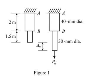
Refer to Figure 1.
Calculate the strain energy
Substitute
Consider that the distance
Calculate the maximum deflection
Substitute
Hence, the maximum deflection of end C is
(b)
The equivalent static load.
(b)
Answer to Problem 46P
The equivalent static load is
Explanation of Solution
Given information:
The mass of the collar D is
The modulus of elasticity of the steel rod is
The length of the rod AB is
The length of the rod BC is
The diameter of rod AB is
The diameter of rod BC is
Calculation:
Refer to part (a).
The maximum deflection of end C is
Calculate the static load
Substitute
Substitute
Therefore, the equivalent static load is
(c)
The maximum stress occurs in the rod.
(c)
Answer to Problem 46P
The maximum stress occurs in the rod is
Explanation of Solution
Given information:
The mass of the collar D is
The modulus of elasticity of the steel rod is
The length of the rod AB is
The length of the rod BC is
The diameter of rod AB is
The diameter of rod BC is
Calculation:
Refer to part (a).
The minimum area of the rod is
Refer to part (b).
The equivalent static load is
Calculate the maximum stress
Substitute
Therefore, the maximum stress occurs in the rod is
Want to see more full solutions like this?
Chapter 11 Solutions
Mechanics of Materials, 7th Edition


- D Fig. P11.71 11.72 Each member of the truss shown is made of steel and has a cross- sectional area of 400 mm². Using E200 GPa, determine the deflection of point D caused by the 16-kN load. 11.73 Each member of the truss shown is made of steel and has a cross- sectional aves of 5 in² Haing F = 20 × 106 vi 16 kN Hi D11 72 1.5 m B E 0.8 marrow_forwardThe length of the 2-mm diameter steel wire CD has been adjusted so that with no load applied, a gap of 1.5mm exists between the end B of the rigid beam ACB and a contact point E. knowing that E = 200 GPa, determine where a 20-kg block should be placed on the beam in order to cause contact between B and E. D 0.23 m 20 kg B с 0.08 m 0.32 marrow_forwardSolve Prob. 10.108 assuming that the 24-lb load is applied at C instead of E.(Reference to Problem 10.108):Two identical rods ABC and DBE are connected by a pin at B and by a spring CE . Knowing that the spring is 4 in. long when unstretched and that the constant of the spring is 8 lb/in., determine the distance x corresponding to equilibrium when a 24-lb load is applied at E as shown.arrow_forward
- Solve Prob. 10.32 assuming that the 900-N vertical force is applied at C instead of E.Reference to Problem 10.32:Two bars AD and DG are connected by a pin at D and by a spring AG . Knowing that the spring is 300 mm long when unstretched and that the constant of the spring is 5 kN/m, determine the value of x corresponding to equilibrium when a 900-N load is applied at E as shown.arrow_forwardA vibration isolation unit consists of two blocks of hard rubber with a modulus of rigidity G= 19 MPa bonded to a plate AB and to rigid supports as shown. Denoting by P the magnitude of the force applied to the plate and by δ the corresponding deflection, determine the effective spring constant, k 5 P/δ, of the system.arrow_forwardPROBLEM 10.21 10.21 The uniform brass bar AB has a rectangular cross section and is supported by pins and brackets as shown. Each end of the bar can rotate freely about a horizontal axis through the pin, but rotation about a vertical axis is prevented by the brackets. (a) Determine the ratio bld for which the factor of safety is the same about the horizontal and vertical axes. (b) Determine the factor of safety if P = 8 L = 2m, d = 38 mm, and E = 105 GPa. B kN,arrow_forward
- A vibration isolation unit consists of two blocks ofhard rubber bonded to a plate AB as shown. A force ofmagnitude P = 24 kN causes a deflection δ = 1.5 mmof the plate AB.(a) Determine the modulus of rigidity (G)of the rubber used.(b) If a rubber having G = 19 MPa is usedand denoting P the magnitude of the forceapplied to AB and by δ the correspondingdeflection, determine the equivalent springconstant k = P/δ of the system.arrow_forwardEach of the five struts shown consists of a solid steel rod. (a) Know-ing that strut (1) is of a 0.8-in. diameter, determine the factor of safety with respect to buckling for the loading shown. (b) Determine the diameter of each of the other struts for which the factor of safety is the same as the factor of safety obtained in part a. Use E=29 *106 psiarrow_forwardKnowing that the ultimate load for cable BD is 100 kN and that a factor of safety of 2.4 with respect to cable failure is required, determine the magnitude of the largest force P that can be safely applied as shown to member ABC. D 40° 30° B 0.6 m 0.8 m- -0.4 m- The magnitude of the largest force P that can be safely applied is 35.27 kN.arrow_forward
- (a) Considering only buckling in the plane of the structure shown and using Euler’s formula, determine the value of θbetween 0 and 90° for which the allowable magnitude of the load P is maximum. (b) Determine the corresponding maximum value of P knowing that a factor of safety of 3.2 is required. Use E= 29 x 106 psi.arrow_forwardTWO CYLINDRICAL ROPS, AC MADE OF ALUMINUM AND CO MADE OF STEEL, ARE JOINED AT C ARE RESTRAINED BY RIGID SUPPORTS AT A AND D. FOR THE LOADING SHOWN AND KNOWING THAT Ea = 10.4 x 10⁶ psi AND = 29 x 10⁰ psi, AND D₁ (6) THE DEFLECTION 6 DETERMINE (a) THE REACTIONS AT A OF POINT C. 18in A Be 18 kips 10 in 11 in DIAMETER с 10 in →→→→ 0 14 kips 15 in. DIAMETER 8arrow_forwardThe lever AB is attached to the horizontal shaft BC that passes through a bearing and is welded to a fixed support at C . The torsional spring constant of the shaft BC is k ; that is, a couple of magnitude K is required to rotate end B through 1 rad. Knowing that the shaft is untwisted when AB is horizontal, determine the value of 0 corresponding to the position of equilibrium when P = 100 N, I= 250 mm, and K = 12.5 N.m/rad.arrow_forward
 Elements Of ElectromagneticsMechanical EngineeringISBN:9780190698614Author:Sadiku, Matthew N. O.Publisher:Oxford University Press
 Mechanics of Materials (10th Edition)Mechanical EngineeringISBN:9780134319650Author:Russell C. HibbelerPublisher:PEARSON
 Thermodynamics: An Engineering ApproachMechanical EngineeringISBN:9781259822674Author:Yunus A. Cengel Dr., Michael A. BolesPublisher:McGraw-Hill Education
 Control Systems EngineeringMechanical EngineeringISBN:9781118170519Author:Norman S. NisePublisher:WILEY
 Mechanics of Materials (MindTap Course List)Mechanical EngineeringISBN:9781337093347Author:Barry J. Goodno, James M. GerePublisher:Cengage Learning
 Engineering Mechanics: StaticsMechanical EngineeringISBN:9781118807330Author:James L. Meriam, L. G. Kraige, J. N. BoltonPublisher:WILEY