
Concept explainers
Videos
through 13.6 Calculate the reactions at points A and BFor the beams shown.
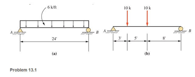
a.
The reaction forces at points A and B
Answer to Problem 13.1P
Explanation of Solution
Given:
The beam diagram and loading are given as shown below:
Concept Used:
Replacing the uniformly distribute load by a concentrated external load
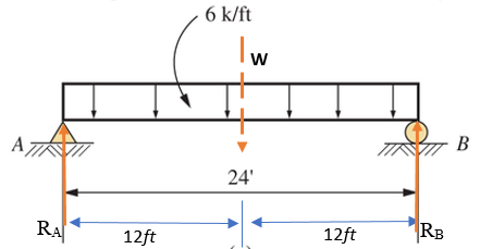
Calculation:
Taking anticlockwise moment positive, the summation of all moment of forces at point A equals to zero
For vertical equilibrium, the summation of forces in vertical direction must be zero
Conclusion:
Therefore, the reaction force at points A,
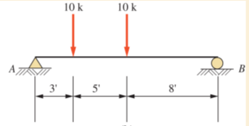
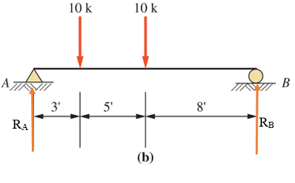
b.
The reaction forces at points A and B
Answer to Problem 13.1P
Explanation of Solution
Given:
The beam diagram and loading are given as shown below
Concept Used:
The reaction forces at point A and B are shown below in the figure and assumed to act in the upward (positive) direction
Calculation:
Taking anticlockwise moment positive, the summation of all moment of forces at point A equals to zero
For vertical equilibrium, the summation of forces in vertical direction must be zero
Conclusion:
Therefore, the forces are
Want to see more full solutions like this?
Chapter 13 Solutions
Applied Statics and Strength of Materials (6th Edition)
Additional Engineering Textbook Solutions
Engineering Mechanics: Statics & Dynamics (14th Edition)
Mechanics of Materials (10th Edition)
Mechanics of Materials
Automotive Technology: Principles, Diagnosis, and Service (5th Edition)
INTERNATIONAL EDITION---Engineering Mechanics: Statics, 14th edition (SI unit)
Thinking Like an Engineer: An Active Learning Approach (4th Edition)


- Calculate the support reactions at A and B for the loaded beam. Ax = ? Ay= ? By=?arrow_forwardAnalyze the cantilever beam shown:arrow_forwardDraw the SFD and BMD for the beams loaded as shown in Calculate the position and magnitude of maximum bending moment and locate points of contra-flexures if any.arrow_forward
- For the following beams compute the vertical and horizontal reactions.arrow_forwardCalculate and draw sheer and moment diagram. Beam is 12ft long with pin connections on both sides. There are 100lb forces at 45 degrees on each end of the beam at 0ft and 12ft.arrow_forward6.38 Compute the value of EId at the right end of the cantilever beam.arrow_forward
 Elements Of ElectromagneticsMechanical EngineeringISBN:9780190698614Author:Sadiku, Matthew N. O.Publisher:Oxford University Press
 Mechanics of Materials (10th Edition)Mechanical EngineeringISBN:9780134319650Author:Russell C. HibbelerPublisher:PEARSON
 Thermodynamics: An Engineering ApproachMechanical EngineeringISBN:9781259822674Author:Yunus A. Cengel Dr., Michael A. BolesPublisher:McGraw-Hill Education
 Control Systems EngineeringMechanical EngineeringISBN:9781118170519Author:Norman S. NisePublisher:WILEY
 Mechanics of Materials (MindTap Course List)Mechanical EngineeringISBN:9781337093347Author:Barry J. Goodno, James M. GerePublisher:Cengage Learning
 Engineering Mechanics: StaticsMechanical EngineeringISBN:9781118807330Author:James L. Meriam, L. G. Kraige, J. N. BoltonPublisher:WILEY