
Concept explainers
Videos
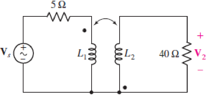
Obtain an expression for V2/Vs in the circuit of Fig. 13.68 if (a) L1 = 100 mH, L2 = 500 mH, and M is its maximum possible value; (b) L1 = 5L2 = 1.4 H and k = 87% of its maximum possible value; (c) the two coils can be treated as an ideal transformer, the left-hand coil having 500 turns and the right-hand coil having 10,000 turns.
FIGURE 13.68
(a)
Find the expression for
Answer to Problem 54E
The expression for
Explanation of Solution
Given data:
Refer to Figure 13.68 in the textbook for the given circuit.
The circuit parameters are given as follows:
Formula used:
Write the expression for reactance due to inductive coil of self-inductance as follows:
Here,
Write the expression for reactance due to inductive coil of mutual-inductance as follows:
Here,
Write the expression for mutual inductance as follows:
Here,
Calculation:
The maximum possible value of
Substitute 1 for
Observer the dot notation in the circuit, use the expression in Equations (1), (2), and apply KVL to the primary winding-loop in the given circuit as follows:
Simplify the expression as follows:
Substitute
Observer the dot notation, use the expression in Equations (1), (2), and apply KVL to the secondary winding-loop in the given circuit as follows:
Substitute
Substitute
From the given circuit, write the expression for
Rearrange the expression as follows:
Substitute
Rearrange the expression as follows:
Conclusion:
Thus, the expression for
(b)
Find the expression for
Answer to Problem 54E
The expression for
Explanation of Solution
Given data:
The circuit parameters are given as follows:
Calculation:
Find the value of
Substitute 0.87 for
Substitute 1.4 H for
Substitute 0.28 H for
Substitute
Substitute
Rearrange the expression as follows:
Conclusion:
Thus, the expression for
(c)
Find the expression for
Answer to Problem 54E
The expression for
Explanation of Solution
Given data:
The circuit parameters are given as follows:
Formula used:
Write the expression for transformer ratio as follows:
Here,
Write the expression for input impedance of the transformer as follows:
Here,
From the given circuit, write the expression for current through primary winding of the transformer as follows:
Calculation:
Substitute 500 for
Substitute 20 for
Substitute
From the given circuit, write the expression for
From Equation (12), substitute
Write the expression for transformer ratio in terms of voltages as follows:
Substitute 20 for
Rearrange the expression as follows:
Conclusion:
Thus, the expression for
Want to see more full solutions like this?
Chapter 13 Solutions
Loose Leaf for Engineering Circuit Analysis Format: Loose-leaf


- An ideal auto-transformer has its secondary winding labelled as a, b and c. The primary winding has 100 turns. The number of turns on the secondary side are 400 turns between a and b and 200 turns between b and c. The total number of turns between a and c is 600 turns. The transformer supplies a resistive load of 6 kW between a and c. In addition, a load of impedance 1,000 cis (45°) ohms is connected between a and b. For a primary voltage of 1,000 V, find the primary current and primary input power.arrow_forwardGe 10:1 m Thanks Any help will be appreciated. S BL • I am doing a AC DC 12 W Regulated power supply with 110 vrms and 60HZ as an input, and I need an output of 6v and 9 V. I have the designed already: the step-down transformer, Resistor as a current limiter to protect the Zener diode, a capacitor for the ripple voltage, and a 2 state switch ( when the switch is closed to the RL will give 9 V and when is closed to the S will give 6V as an output). • I need some support with some calculations to find PIV for each diode // Average Power// some calculations in how to find the values for the resistors and capacitors to accomplish the desire output // and some calculations for the ripple voltage. Note: the Zener is regulated to 9v. I know the RL>R to get the desire output.arrow_forwardAn ideal transformer has two secondary coils with number of turns 100 and 150respectively. Theprimary coil has 125 turns and supplied from 400 V, 50 Hz,single phase source. If the two secondarycoils are connected in series, the possible voltages across the series combination will be:(A) 833.5 V or 166.5 V (B) 833.5 V or 320 V (C) 320 V or 800 V (D) 800 V or 166.5 Varrow_forward
- IV- Transformer Design You are requested to design a transformer which will have the following characteristics: Two windings, one primary and one secondary with an E-shape core. Vin = 220 V RMS 16 s Vout < 20 v RMS open circuits 14.5 V < Vout s 16 V on a 100 N resistor. 2 VA < S 35 VA apparent power. Show all steps of your design with calculation. - Indicate current in primary and secondary in both open circuit and with 100 n resistor. Simulate your transformer and show both input and output voltage with the 100 Ω load. Talk about your transformer and wire sizes.arrow_forwardA 100KVA, 250 V/200KV feed transformer has resistance and reactance of 1% and 5% respectively. This transformer is used to test a cable at 400 KV at 50 Hz The cable takes a charging current of 0.5A at 400KV. Determine the series inductance required. Assume 1% resistance of inductor. Also determine input voltage to the transformer. Neglect dielectric loss of the cable.arrow_forwardAn ideal transformer is rated 12 kVA, 3600/120V, 60 Hz. Find the transformation ratio if the 120V is the secondary voltage. a = Find the current rating of the secondary if the 120V is the secondary voltage. units Is rating Find the current rating of the primary if the 120V is the secondary voltage. Ip rating unitsarrow_forward
- (S) Primary AC Source Transformer Secondary Figure 6 AC/DC Full-wave Rectifier Capaictor Non- linear Load, Explain how harmonic are formed through different sources, which you have identified in above power system circuit and analyse the effects of harmonic through logical development of principles.arrow_forwardIn the circuit shown in the figure below, if the primary coil has the number of turns of 18, then the number of turns in the secondary coil required, such that maximum power will be delivered to the load of 50 is. 45 0 ww Ideal Transformer ww 00000,arrow_forwardA transformer has 150 primary turns and 75 secondary turns. Its primary is excited at 200 V and the secondary is loaded with an impedance of 5 <30° Ω. Calculate the primary current and its pf. State assumptions madearrow_forward
- 1. Find the h-parameters of the ideal transformer given below (30 p- 20 min). 10 1H 1 H 2Harrow_forward3- The self-inductance of an iron-cored coil is a function of: a) The geometry of the coil only. b) The current passing through it only. c) The frequency of the applied voltage only. d) All of the above factors. 4- The most effootiuaarrow_forwardQ1) A 20KVA , 2000/200 V single phase ,50 Hz transformer has a primary resistance of 2.5 0 and reactance of 4.8 Q .the secondary resistance and reactance are 0.01 Q and 0.018 0 respectively .find a- equivalent resistance ,reactance and impedance referred to primary. b- equivalent resistance ,reactance and impedance referred to secondary.arrow_forward
 Introductory Circuit Analysis (13th Edition)Electrical EngineeringISBN:9780133923605Author:Robert L. BoylestadPublisher:PEARSON
 Delmar's Standard Textbook Of ElectricityElectrical EngineeringISBN:9781337900348Author:Stephen L. HermanPublisher:Cengage Learning
 Programmable Logic ControllersElectrical EngineeringISBN:9780073373843Author:Frank D. PetruzellaPublisher:McGraw-Hill Education
 Fundamentals of Electric CircuitsElectrical EngineeringISBN:9780078028229Author:Charles K Alexander, Matthew SadikuPublisher:McGraw-Hill Education
 Electric Circuits. (11th Edition)Electrical EngineeringISBN:9780134746968Author:James W. Nilsson, Susan RiedelPublisher:PEARSON
 Engineering ElectromagneticsElectrical EngineeringISBN:9780078028151Author:Hayt, William H. (william Hart), Jr, BUCK, John A.Publisher:Mcgraw-hill Education,