
Videos
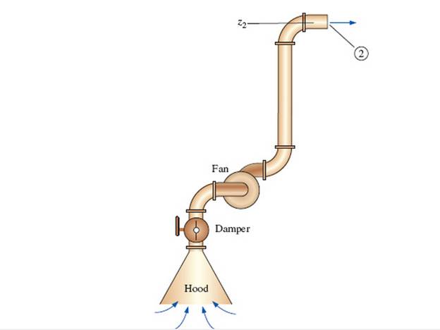
A local ventilation system (a hood and duct system) is used to remove air and contaminants produced by a welding operation (Fig. P 14-55E). The inner diameter (ID) of the duct is D = 9.06 in, its average roughness is 0.0059 in, and its total length is L = 34.0 ft. There are three elbows along the duct, each with a minor loss coefficient of 0.21. Literature from the hood manufacturer lists the hood entry loss coefficient as 4.6 based on duct velocity. When the damper is fully open, its loss coefficient is 1.8. A squirrel cage centrifugal fan with a 9.0-in inlet is available. Its performance data fit a parabolic curve of the form

The volume flow rate.
Answer to Problem 55EP
The volume flow rate is
Explanation of Solution
Given Information:
The inner diameter of the duct is
Expression for steady energy equation from point 1 in the stagnant air region to point 2 at the duct outlet
Here, the required head for the fan is
Expression for the total head loss
Here, the velocity of the air is
Expression for Reynold's number
Here, the kinematic viscosity is
Expression for relative roughness
Here, the roughness of the pipe is
Expression for the friction factor
Expression for the volume flow rate
Here, the area of the pipe is
Expression for the area of the pipe
Substitute
Expression to convert the shutoff head from inches of water column to inches of air column
Here, the density of the water is
Expression to convert
Calculation:
Refer to the Table-A-9E, "Properties of air at 1 atm pressure" to obtain the density of the air as
Substitute
Substitute
Substitute
Substitute
Substitute
Substitute
Substitute
Substitute
Substitute
Substitute
Since at the operating point the available head and the required head are equal, therefore equate equation (XII) and (XIII).
Solve Equation (XII) and Equation (XIV) to obtain the value of velocity as
Substitute
Conclusion:
The volume flow rate is
Want to see more full solutions like this?
Chapter 14 Solutions
Fluid Mechanics: Fundamentals and Applications


- As an engineer, you are setting up an experiment to measure the airflow rate in a duct. Choose a technique and devices for the measurement. You are required to design/draw the set-up and demonstrate the calculation for themeasurement of flow rate. Please discuss the relevant principle involved and reason for selectingthe technique.arrow_forwardPUMP SYSTEM – SYSTEM CURVE AND NPSH The pumping system shown below consists of a suction pipe of length 3m and diameter 80mm; delivery pipe of length 6m and diameter 80mm; 4 elbows, each with a loss coefficient of k = 0.3; total static lift = 6m; tank entry and exit loss coefficients 0.5 and 1.0, respectively; suction and delivery pipe friction factor f = 0.007Darcy. A Robuschi 150-500 pump rotates at 1470 rpm and the desired flow rate is a minimum of 200 m3/h. SUCTION PIPE Complete the following tasks: 1. Draw the system curve as described above on the Roubuschi pump curve data sheet supplied. Work in increments of Q 50m3/h starting at 0 (7-point curve) 2. Would you advise the client to select the p400 or ¢460 impeller? Give two reasons for your answer. If the 400 impeller is used: Assume: the gauge pressure in the suction tank at 115 kPa, the vapour pressure of the water at its average operating temperature at 20C suction height as 1.5 m. 3. Is the pump likely to cavitate? Support…arrow_forwardBA4s6nknAPkVXhnUEg rmResponse Good Luck... PROBLEM 1 Determine the following: a. Enclosed Area b. Perimeter of the thin walled tube Given is a thin-walled tube with the following data: Wall thickness-2mm ABC is a sector with a radius of 50 mm AOD & COD is a triangle C. Shear flow d. Shear stress e. Angle of twist Torque is 1000 N.m Length of the thin walled tube is 0.5 m Use G=24 GPa for aluminium A 90 B D 3R PROBLEM 2 Determine the following: a. Enclosed Area b. Perimeter of the thin walled tube c. Shear flow d. Shear stress Given is a thin-walled tube with the following data: Wall thickness- 3mm Torque is 900 N.m Length of the thin walled tube is 1.2 m. Use G=24 GPa for aluminium e. Angle of twist Ps Xd étv Warrow_forward
- CORRECT LETTER PLS 1. In laminar flow, which is correct?BJ: higher Re value has higher friction factorJB: lower Re value has higher friction factorGroup of answer choices A. BJ is false and JB is true B. BJ is true and JB is false C. BJ is false and JB is false D. BJ is true and JB is true 2.In turbulent flow, which is correct?BJ: higher Re value has lower friction factorJB: lower Re value has higher friction factorGroup of answer choices A.BJ is true and JB is true B.BJ is false and JB is false C. BJ is false and JB is true D. BJ is true and JB is false 3. In a system with 4 reservoirs and 1 pipe junction, how many continuity equations are formulable?Group of answer choices A. 2 B. 3 C. 5 D. 4 E. 1arrow_forwardAssume a car's exhaust system an be approximated as pipe that is 14 feet long with a diameter of 0.125 ft and is cast-iron (roughness of ɛ=0.00085 feet). This pipe also has six 90° flanged elbows (each with KL=0.3) and a muffler (KL=8.5). MIDAS K =8,52) (1) KLel = 0.3 Determine the pressure at the beginning of the exhaust system if the flowrate is 0.10 cubic feet per second or ft/sec, the termperature of the air is 250°F and the exhaust has the same properties as air. Useful values: R = 1716 ft-lbf/slug-OR Viscosity of air at 250°F is 4.7x10⁻⁷ Ibf-s/ft2 Density of air at 250°F is 1.74x10⁻³ slug/ft3 What is the Reynolds number for this flow? What is the velocity in ft/s of the air in the exhaust? What is the gauge pressure at P1 in Ibf/ft?arrow_forwardQ: Select duct sizes for the rectangular duct system shown in the Figure, using the equal friction method. The total pressure available for the duct system is 0.12 in. wg (30 Pa), and the loss in total pressure for each diffuser at the specified flow rate is 0.02 in. wg (5 Pa). Assume the velocity in mean duct 600 fpm. 25 ft (8 m) 150 cfm (0.071 m/s) Plenum Boots are round (2) 5 ft to rectangular. 20 ft (6 m) 15 ft (4.6 m) (1.5 m) (1.5 m) 200 cfm 5 ft 150 cfm 5 ft (0.095 m/s) (0.071 m/s) (1.5 m) 5 ft (1.5 m) E (1.5 m)arrow_forward
- last three digits of your number for the upstream pressure: 754arrow_forwardPUMP SYSTEM - SYSTEM CURVE AND NPSH SUBMIT BY 8 MAY 2022 The pumping system shown below consists of a suction pipe of length 3m and diameter 80mm; delivery pipe of length 6m and diameter 80mm; 4 elbows, each with a loss coefficient of k = 0.3; total static lift = 6m; tank entry and exit loss coefficients 0.5 and 1.0, respectively; suction and delivery pipe friction factor f = 0.007Daroy. A Robuschi 150-500 pump rotates at 1470 rpm and the desired flow rate is a minimum of 200 m/h. Complete the following tasks: 1. Draw the system curve as described above on the Roubuschi pump curve data sheet supplied. Work in increments of Q 50m³/h starting at 0 (7-point curve) 2. Would you advise the client to select the 400 or 460 impeller? Give two reasons for your answer. If the 400 impeller is used: Assume: the gauge pressure in the suction tank at 115 kPa, • the vapour pressure of the water at its average operating temperature at 20C • suction height as 1.5 m. 3. Is the pump likely to cavitate?…arrow_forwardQ-2 ) ) A boiler house has natural draught chimney of 20 m height. Flue gases are at temperature of 380°C and ambient temperature is 27°C. Determine the draught in mm of water column for maximum discharge through chimney and also the air supplied per kg of fuel. Ans. [11.77 mm of water, 11.32 kg/kg of fuelarrow_forward
- 10-1. The piping of Fig. 10-50 is all the same size and part of a larger water distribution system. Figure 10-50 Sketch for Problem 10-1. Toblems Uj23 - 20t (6m) U34- 15t (4.6m) H, = B0ft (24m) Pump PROBLEMS (a) Compute the pressure at points 2, 3, and 4 if the pressure at point 1 is 20 psig (138 kPa gage). (b) Sketch the system characteristic for the complete run of pipe. Assume a flow rate of 150 gpm (9.5 L/s).arrow_forward13. For the same value of Reynolds number friction factor for steady laminar for circular pipe is greater than that for the flow between parallel plates. (T/F) 14. Pipe roughness is important for turbulent flow only. (T/F) 15. A 1 cmx 20 cm sheet of water is deflected as shown in Figure. The magnitude of the horizontal force acting on the stationary deflector is nearest....... a) 6830 N b) 5000 N d)2500 N e) none of thesearrow_forwardfLUID MECAHNICS The flow in the piping system shown is 10 mgd. Determine (a) the head loss from A to D and (b) the flow in pipes 2, 3, and 4. Use C = 100 for all pipes. (a) head loss : _____________________ ft of water(b)Flow in Pipe 2: _____________________ mgd Pipe 3: _____________________ mgd Pipe 4: _____________________ mgdarrow_forward
 Principles of Heat Transfer (Activate Learning wi...Mechanical EngineeringISBN:9781305387102Author:Kreith, Frank; Manglik, Raj M.Publisher:Cengage Learning