
Concept explainers
Videos
Ruby, with mass 55.0 kg, is trying to reach a box on a high shelf by standing on her tiptoes. In this position, half her weight is supported by the normal force exerted by the floor on the toes of each foot as shown in Figure P14.75A. This situation can be modeled mechanically by representing the force on Ruby’s Achilles tendon with
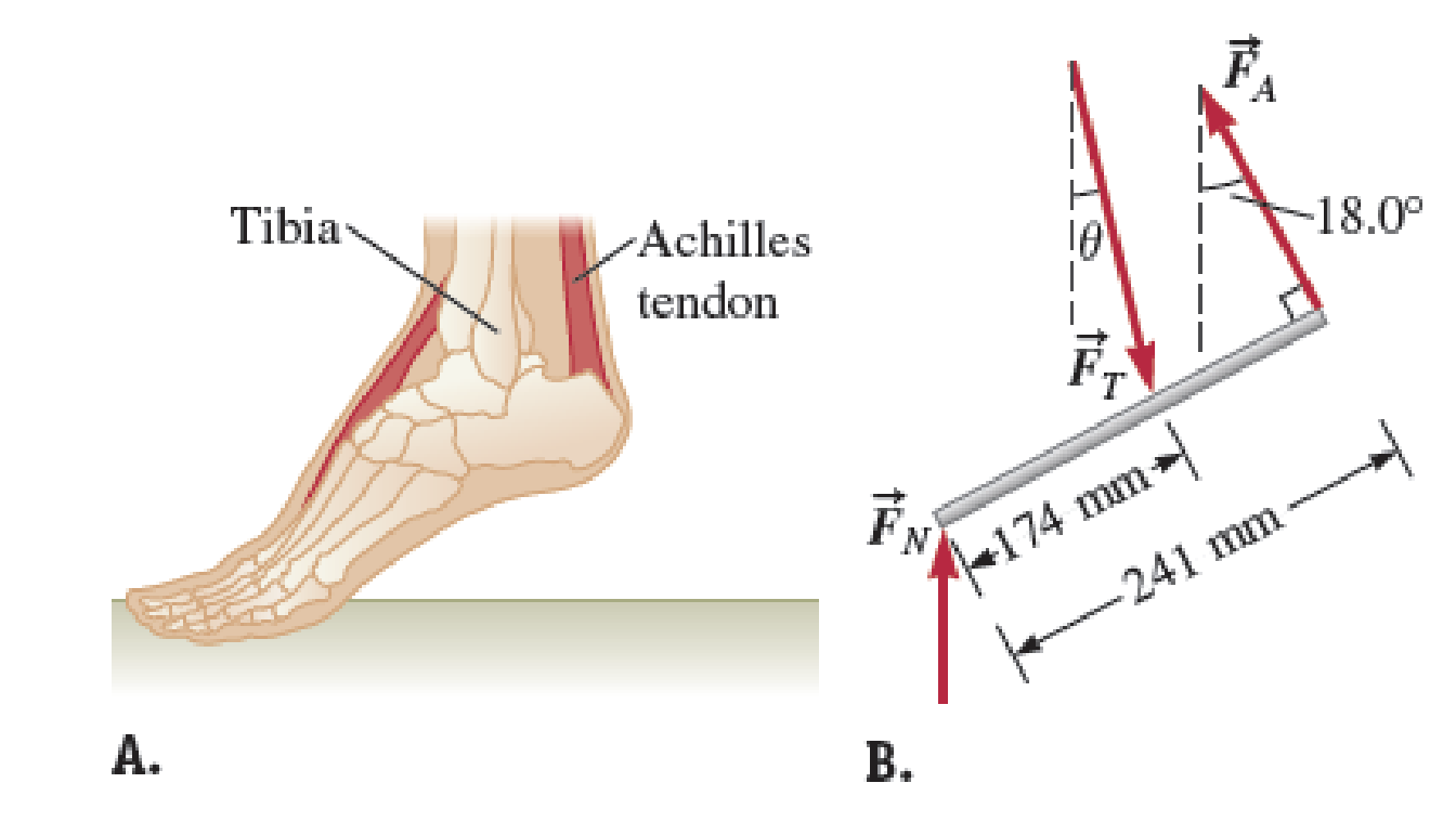
FIGURE P14.75
Want to see the full answer?
Check out a sample textbook solution
Chapter 14 Solutions
Physics for Scientists and Engineers: Foundations and Connections


- A bridge of length 50.0 m and mass 8.00 104 kg is supported on a smooth pier at each end as shown in Figure P12.25. A truck of mass 3.00 104 kg is located 15.0 m from one end. What are the forces on the bridge at the points of support? Figure P12.25arrow_forwardWhen a person stands on tiptoe on one foot (a strenuous position), the position of the foot is as shown in Figure P12.32a. The total gravitational force Fg on the body is supported by the normal force n exerted by the floor on the toes of one foot. A mechanical model of the situation is shown in Figure P12.32b, where T is the force exerted on the foot by the Achilles tendon and R is the force exerted on the foot by the tibia. Find the values of T, R, and when Fg = 700 N. Figure P12.32arrow_forwardA massless, horizontal beam of length L and a massless rope support a sign of mass m (Fig. P14.78). a. What is the tension in the rope? b. In terms of m, g, d, L, and , what are the components of the force exerted by the beam on the wall? FIGURE P14.78arrow_forward
- A 215-kg robotic arm at an assembly plant is extended horizontally (Fig. P14.32). The massless support rope attached at point B makes an angle of 15.0 with the horizontal, and the center of mass of the arm is at point C. a. What is the tension in the support rope? b. What are the magnitude and direction of the force exerted by the hinge A on the robotic arm to keep the arm in the horizontal position? FIGURE P14.32arrow_forwardWhy is the following situation impossible? A worker in a factory pulls a cabinet across the floor using a rope as shown in Figure P12.36a. The rope make an angle = 37.0 with the floor and is tied h1 = 10.0 cm from the bottom of the cabinet. The uniform rectangular cabinet has height = 100 cm and width w = 60.0 cm, and it weighs 400 N. The cabinet slides with constant speed when a force F = 300 N is applied through the rope. The worker tires of walking backward. He fastens the rope to a point on the cabinet h2 = 65.0 cm off the floor and lays the rope over his shoulder so that he can walk forward and pull as shown in Figure P12.36b. In this way, the rope again makes an angle of = 37.0 with the horizontal and again has a tension of 300 N. Using this technique, the worker is able to slide the cabinet over a long distance on the floor without tiring. Figure P12.36 Problems 36 and 44.arrow_forwardWhy is the following situation impossible? A uniform beam of mass mk = 3.00 kg and length = 1.00 m supports blocks with masses m1 = 5.00 kg and m2 = 15.0 kg at two positions as shown in Figure P12.2. The beam rests on two triangular blocks, with point P a distance d = 0.300 m to the right of the center of gravity of the beam. The position of the object of mass m2 is adjusted along the length of the beam until the normal force on the beam at O is zero. Figure P12.2arrow_forward
- A uniform sign of weight Fg and width 2L hangs from a light, horizontal beam hinged at the wall and supported by a cable (Fig. P12.31). Determine (a) the tension in the cable and (b) the components of the reaction force exerted by the wall on the beam in terms of Fg, d, L, and . Figure P12.31arrow_forwardA uniform beam of length 7.60 m and weight 4.50 102 N is carried by two workers, Sam and Joe, as shown in Figure P12.6. Determine the force that each person exerts on the beam. Figure P12.6arrow_forwardA stepladder of negligible weight is constructed as shown in Figure P12.40, with AC = BC = . A painter of mass m stands on the ladder a distance d from the bottom. Assuming the floor is frictionless, find (a) the tension in the horizontal bar DE connecting the two halves of the ladder, (b) the normal forces at A and B, and (c) the components of the reaction force at the single hinge C that the left half of the ladder exerts on the right half. Suggestion: Treat the ladder as a single object, but also treat each half of the ladder separately. Figure P12.40 Problems 40 and 41.arrow_forward
 Physics for Scientists and Engineers: Foundations...PhysicsISBN:9781133939146Author:Katz, Debora M.Publisher:Cengage Learning
 Physics for Scientists and Engineers with Modern ...PhysicsISBN:9781337553292Author:Raymond A. Serway, John W. JewettPublisher:Cengage Learning
 Physics for Scientists and EngineersPhysicsISBN:9781337553278Author:Raymond A. Serway, John W. JewettPublisher:Cengage Learning