
Videos
(a)
Design a circuit which produces a transfer function of
(a)
Explanation of Solution
Given data:
The given transfer function is,
Calculation:
The transfer function of the circuit is,
The above transfer function has a zero at
The Figure 14.39 (b) in the textbook, that shows a cascade two stages of the circuit with a zero at
For a single zero,
Substitute
Consider the value of
Substitute
Transfer function:
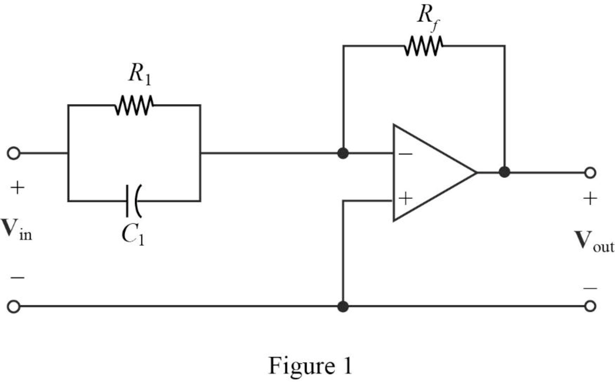
The input impedance of the cascaded circuit in Figure 1 is,
Then, write the Formula for the transfer function for the cascaded two stage amplifier.
Substitute
Thus, the transfer function for
Substitute 1 for
Completing the design by letting
If the input will be inverted, add an inverting amplifier with gain of 1 to provide the transfer function as follows.
Thus, the final design of the circuit is,
Conclusion:
Thus, a circuit is designed which produces a transfer function of
(b)
Design a circuit which produces a transfer function of
(b)
Explanation of Solution
Given data:
The given transfer function is,
Calculation:
The transfer function of the circuit is,
The above transfer function has pole at
The Figure 14.39 (a) in the textbook, that shows a cascade two stages of the circuit with pole at
For pole
Substitute
Let arbitrarily consider
Substitute
Transfer function:
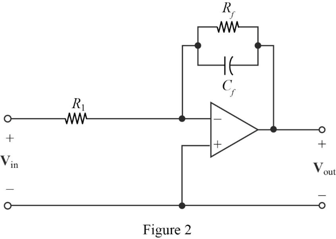
Find the feedback impedance of the cascaded circuit in Figure 2.
Write the formula for the transfer function of the cascaded circuit in Figure 2 as follows
Substitute
Therefore, consider the transfer function
Substitute 1 for
Completing the design by letting
If the input will be inverted, add an inverting amplifier with gain of 1 to provide the transfer function as follows.
Thus, the final design of the circuit is,
Conclusion:
Thus, a circuit is designed which produces a transfer function of
(c)
Design a circuit which produces a transfer function of
(c)
Explanation of Solution
Given data:
The given transfer function is,
Calculation:
The transfer function of the circuit is,
For the above transfer function, it has a zero at
Refer to Figure 1 in Part (a), that shows a cascade two stages of the circuit with a zero at
For a single zero,
Substitute
Let arbitrarily consider
Substitute
Consider the same circuit shown in Figure 1 and the transfer function as in a cascaded circuit,
Substitute 1 for
Completing the design by letting
Thus, the final design of the circuit is,
The given transfer function has a pole at
Refer to Figure 2 in Part (b), that shows a cascade two stages of the circuit with pole at
For pole
Substitute
Let arbitrarily consider
Substitute
The above equation becomes,
Consider the same circuit shown in Figure 2 and the transfer function as in a cascaded circuit,
Substitute 2 for
Completing the design by letting
Thus, the final design of the circuit is,
Therefore, the overall transfer function of the cascaded circuit is,
Substitute
Conclusion:
Thus, a circuit is designed which produces a transfer function of
Want to see more full solutions like this?
Chapter 14 Solutions
Loose Leaf for Engineering Circuit Analysis Format: Loose-leaf


- Q5. Compute the Transfer Function of the depicted block diagram. A) N(s) R(s) 100 10 10 C(s) s2 + 140s + 100 0.1s+1 20s + 1arrow_forwardConsider the transfer function G(s) 5 s² +as+5 Select the answer closest to the value a for which the step response will have a rise time (within 30%) of .2 seconds. (a) 6.4 (b) 4.4 (c) 2.1 = (d) 1.05 (e) None of the above/ Specification cannot be satisfiedarrow_forwardFor the system described by its open loop transfer function: s+1 G(s) = k- Construct the root locus of this system by changing k in the interval [0, 0). 0.1s4+1.6s3+6s2arrow_forward
- 2. Consider the following transfer function model W(s) = 1 s5 +10s +35³ +50s² +24s +11 Use the Hurwitz criterion to determine if the closed-loop system is stable: W(s)arrow_forwardThe step response of an LTI system is s[n] and it is shown in the following figure. a) What is the impulse response of this system? b) Plot s:[n] = 1+ s[-2n].arrow_forward4) The transfer function of a system is given as H(s) = a) Poles b) Zeros c) Stability using pole zero map. 3s+6 53 +35² +7s+5 Find,arrow_forward
- I. Find the equivalent transfer function, G(s) C(s)/ R(s), for the systems shown below. The transfer function must be expressed as single term rational function. Example: Correct format: G(s) = Incorrect formats: G(s) = 1. +25+2+3= G(S) = (252)), G(s); = 5-1 R(s) + " 5s²-2 53-3545 -1th 50 ellm 2 C(s) -451-0-0--arrow_forward2. (a) Derive the expression for vout(t) in terms of vin(t), or (b) Derive the transfer function T(s) = Vout(s)/ Vin(s). C1 R1 ideal R2 vout vin R3 C2arrow_forwardSuppose we have the following transfer function: K(s² – 10s + 1) 2s4 + 4s3 – s + 11 + K` Gp(8) a. Express the system in state-space form. b. Translate the state-space form into block diagram format.arrow_forward
- a. Reduce the following block diagram into a single functional block and determine transfer function C(s)/R(s) b. Determine the range of K for stability for the system shown in the figure. s + 22 s + 3 R(s) K C(s) S 1 s +7arrow_forwardFor the following circuit, answer to the given questions. Vo - C1 L1 3[H] 0.0125[F] R2 28[2] { R1 $10[2] L2 2[H] V,(8) a) Find out a transfer function, H(s)= V(s) b) Obtain the poles and zeros of H(s) obtained in a) (If there are no poles and/or zeros, just answer "No poles" and/or “No zeros"). c) For the given input, v¡(t) = 4e-2tu(t) [V], find out the output v,(t) .arrow_forward2. (a) Derive the expression for vout(t) in terms of vin(t), or (b) Derive the transfer function T(s) = Vout(s)/Vin(s). R1 ideal R2 vout vin R3arrow_forward
 Introductory Circuit Analysis (13th Edition)Electrical EngineeringISBN:9780133923605Author:Robert L. BoylestadPublisher:PEARSON
 Delmar's Standard Textbook Of ElectricityElectrical EngineeringISBN:9781337900348Author:Stephen L. HermanPublisher:Cengage Learning
 Programmable Logic ControllersElectrical EngineeringISBN:9780073373843Author:Frank D. PetruzellaPublisher:McGraw-Hill Education
 Fundamentals of Electric CircuitsElectrical EngineeringISBN:9780078028229Author:Charles K Alexander, Matthew SadikuPublisher:McGraw-Hill Education
 Electric Circuits. (11th Edition)Electrical EngineeringISBN:9780134746968Author:James W. Nilsson, Susan RiedelPublisher:PEARSON
 Engineering ElectromagneticsElectrical EngineeringISBN:9780078028151Author:Hayt, William H. (william Hart), Jr, BUCK, John A.Publisher:Mcgraw-hill Education,