
Statics and Mechanics of Materials (5th Edition)
5th Edition
ISBN: 9780134382593
Author: Russell C. Hibbeler
Publisher: PEARSON
expand_more
expand_more
format_list_bulleted
Videos
Textbook Question
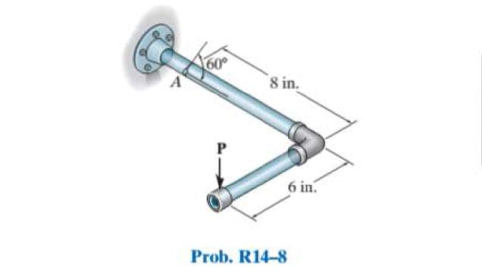
Chapter 14, Problem 8RP
A single strain gage, placed in the vertical plane on the outer surface and at an angle 60° to the axis of the pipe, gives a reading at point A of
Expert Solution & Answer
Want to see the full answer?
Check out a sample textbook solution
Students have asked these similar questions
The 60° strain rosette is mounted on the surface of the bracket. The following readings are obtained for each gage: Pa = -780(10-6), Pb = 400(10-6), and Pc = 500(10-6). Determine (a) the principal strains and (b) the maximumin-plane shear strain and associated average normal strain. In each case show the deformed element due to these strains.
The state of strain at the point on the gear tooth has
components €x = 850(106), €y = 480(106), Yxy =
650(106). Use the strain-transformation equations to
determine (a) the in-plane principal strains and (b) the
maximum in-plane shear strain and average normal strain.
In each case specify the orientation of the element and
show how the strains deform the element within the
x-y plane.
The 60o strain rosette is mounted on a beam. The following readings are obtained for each gage: ϵa = 650(10-6), ϵb = -550(10-6), and ϵc =470(10‑6). Determine (a) the in-plane principal strains and (b) maximum in plane shear strain.
Chapter 14 Solutions
Statics and Mechanics of Materials (5th Edition)
Ch. 14.3 - In each ease, the state of stress x, y, xy...Ch. 14.3 - Given the state of stress shown on the element,...Ch. 14.3 - Determine the normal stress and shear stress...Ch. 14.3 - Prob. 2FPCh. 14.3 - Determine the equivalent state of stress on an...Ch. 14.3 - Prob. 4FPCh. 14.3 - The beam is subjected to the load at its end....Ch. 14.3 - Prob. 6FPCh. 14.3 - Prove that the sum of the normal stresses x+y=x+y...Ch. 14.3 - Determine the stress components acting on the...
Ch. 14.3 - Determine the stress components acting on the...Ch. 14.3 - Determine the normal stress and shear stress...Ch. 14.3 - Determine the normal stress and shear stress...Ch. 14.3 - Prob. 6PCh. 14.3 - Prob. 7PCh. 14.3 - Determine the stress components acting on the...Ch. 14.3 - Determine the stress components acting on the...Ch. 14.3 - Determine the stress components acting on the...Ch. 14.3 - Determine the equivalent state of stress on an...Ch. 14.3 - Prob. 12PCh. 14.3 - Determine the stress components acting on the...Ch. 14.3 - Determine (a) the principal stresses and (b) the...Ch. 14.3 - Prob. 15PCh. 14.3 - Prob. 16PCh. 14.3 - Prob. 17PCh. 14.3 - Prob. 18PCh. 14.3 - Prob. 19PCh. 14.3 - Prob. 20PCh. 14.3 - Prob. 21PCh. 14.3 - The state of stress at a point in a member is...Ch. 14.3 - The wood beam is subjected to a load of 12 kN. If...Ch. 14.3 - Prob. 24PCh. 14.3 - The internal loadings at a section of the beam are...Ch. 14.3 - The internal loadings at a section of the beam are...Ch. 14.3 - Prob. 27PCh. 14.3 - Prob. 28PCh. 14.3 - The beam has a rectangular cross section and is...Ch. 14.3 - A paper tube is formed by rolling a cardboard...Ch. 14.3 - Prob. 31PCh. 14.3 - The 2-in.-diameter drive shaft AB on the...Ch. 14.3 - Determine the principal stresses in the...Ch. 14.3 - The internal loadings at a cross section through...Ch. 14.3 - The internal loadings at a cross section through...Ch. 14.3 - Prob. 36PCh. 14.3 - The steel pipe has an inner diameter of 2.75 in....Ch. 14.3 - Prob. 38PCh. 14.3 - The wide-flange beam is subjected to the 50-kN...Ch. 14.3 - Prob. 40PCh. 14.3 - The box beam is subjected to the 26-kN force that...Ch. 14.3 - The box beam is subjected to the 26-kN force that...Ch. 14.4 - Use Mohrs circle to determine the normal stress...Ch. 14.4 - Prob. 8FPCh. 14.4 - Prob. 9FPCh. 14.4 - Prob. 10FPCh. 14.4 - Prob. 11FPCh. 14.4 - Prob. 12FPCh. 14.4 - Solve Prob. 142 using Mohrs circle. 14-2.Determine...Ch. 14.4 - Solve Prob. 143 using Mohrs circle. 143.Determine...Ch. 14.4 - Determine the stress components acting on the...Ch. 14.4 - Solve Prob. 1410 using Mohrs circle. 149.Determine...Ch. 14.4 - Solve Prob. 1415 using Mohrs circle. 1415.The...Ch. 14.4 - Solve Prob. 1416 using Mohrs circle....Ch. 14.4 - Prob. 49PCh. 14.4 - Determine (a) the principal stresses and (b) the...Ch. 14.4 - Determine (a) the principal stresses and (b) the...Ch. 14.4 - Determine the equivalent state of stress if an...Ch. 14.4 - Draw Mohrs circle that describes each of the...Ch. 14.4 - Draw Mohrs circle that describes each of the...Ch. 14.4 - Determine (a) the principal stresses and (b) the...Ch. 14.4 - Determine (a) the principal stress and (b) the...Ch. 14.4 - Determine (a) the principal stresses and (b) the...Ch. 14.4 - Determine (a) the principal stresses and (b) the...Ch. 14.4 - Determine (a) the principal stresses and (b) the...Ch. 14.4 - Prob. 60PCh. 14.4 - The grains of wood in the board make an angle of...Ch. 14.4 - The post is fixed supported at its base and a...Ch. 14.4 - Determine the principal stresses, the maximum...Ch. 14.4 - The thin-walled pipe has an inner diameter of 0.5...Ch. 14.4 - The frame supports the triangular distributed load...Ch. 14.4 - The frame supports the triangular distributed load...Ch. 14.4 - Prob. 67PCh. 14.4 - The pedal crank for a bicycle has the cross...Ch. 14.4 - A spherical pressure vessel has an inner radius of...Ch. 14.4 - The cylindrical pressure vessel has an inner...Ch. 14.4 - Prob. 71PCh. 14.4 - Determine the principal stress at point D, which...Ch. 14.4 - If the box wrench is subjected to the 50 lb force,...Ch. 14.4 - If the box wrench is subjected to the 50-lb force,...Ch. 14.4 - Prob. 75PCh. 14.5 - Draw the three Mohrs circles that describe each of...Ch. 14.5 - Draw the three Mohrs circles that describe the...Ch. 14.5 - Draw the three Mohrs circles that describe the...Ch. 14.5 - Determine the principal stresses and the absolute...Ch. 14.5 - Prob. 80PCh. 14.5 - Prob. 81PCh. 14.5 - Prob. 82PCh. 14.8 - Prove that the sum of the normal strains in...Ch. 14.8 - The state of strain at the point on the arm has...Ch. 14.8 - The state of strain at the point on the pin leaf...Ch. 14.8 - The state of strain at the point on the pin leaf...Ch. 14.8 - Prob. 88PCh. 14.8 - The state of strain at a point on the bracket has...Ch. 14.8 - Prob. 90PCh. 14.8 - Prob. 91PCh. 14.8 - Prob. 92PCh. 14.8 - Prob. 93PCh. 14.8 - Prob. 94PCh. 14.8 - Prob. 95PCh. 14.8 - Prob. 96PCh. 14.8 - Prob. 97PCh. 14.8 - The state of strain on the element has components...Ch. 14.8 - Solve Prob. 1486 using Mohrs circle. 1486.The...Ch. 14.8 - Solve Prob. 1487 using Mohrs circle. 1486.The...Ch. 14.8 - Solve Prob. 1488 using Mohrs circle. 1488.The...Ch. 14.8 - Solve Prob. 1491 using Mohrs circle. 1491.The...Ch. 14.8 - Solve Prob. 1490 using Mohrs circle. 1489.The...Ch. 14.11 - The strain at point A on the bracket has...Ch. 14.11 - The strain at point A on a beam has components...Ch. 14.11 - The strain at point A on the pressure-vessel wall...Ch. 14.11 - The 45 strain rosette is mounted on the surface of...Ch. 14.11 - Prob. 109PCh. 14.11 - Use Hookes law, Eq. 1432, to develop the strain...Ch. 14.11 - Prob. 111PCh. 14.11 - A rod has a radius of 10 mm. If it is subjected to...Ch. 14.11 - The polyvinyl chloride bar is subjected to an...Ch. 14.11 - The polyvinyl chloride bar is subjected to an...Ch. 14.11 - The spherical pressure vessel has an inner...Ch. 14.11 - Determine the bulk modulus for each of the...Ch. 14.11 - The strain gage is placed on the surface of the...Ch. 14.11 - The principal strains at a point on the aluminum...Ch. 14.11 - Prob. 119PCh. 14.11 - Prob. 120PCh. 14.11 - The cube of aluminum is subjected to the three...Ch. 14.11 - The principal strains at a point on the aluminum...Ch. 14.11 - A uniform edge load of 500 lb/in. and 350 lb/in....Ch. 14.11 - Prob. 124PCh. 14 - The steel pipe has an inner diameter of 2.75 in....Ch. 14 - Prob. 2RPCh. 14 - Prob. 3RPCh. 14 - The crane is used to support the 350-lb load....Ch. 14 - In the case of plane stress, where the in-plane...Ch. 14 - The plate is made of material having a modulus of...Ch. 14 - If the material is graphite for which Eg = 800 ksi...Ch. 14 - A single strain gage, placed in the vertical plane...Ch. 14 - The 60 strain rosette is mounted on a beam. The...
Knowledge Booster


Learn more about
Need a deep-dive on the concept behind this application? Look no further. Learn more about this topic, mechanical-engineering and related others by exploring similar questions and additional content below.Similar questions
- A rectangular aluminum plate of uniform thickness has a strain gauge at the center. It is placed in a test rig which can apply a biaxial force system along the edges of the plate as shown below. If the measured strains are +0.0005 and +0.001 in the x and y directions respectively, a) Determine the corresponding stresses set up in the plate and the strain through the thickness, εz. Take E=72 GPa and ν=0.32. b) Construct the Mohr’s circle for the loaded plate. c) State the values of the principal stresses. d) Determine the maximum shearing stresses and the directions of the planes on which they occur.arrow_forwardThe 45° strain rosette is mounted on the surface of a pressure vessel. The following readings are obtained for each gage: Pa = 475(10-6), Pb = 250(10-6), and Pc = -360(10-6). Determine the in-plane principal strainsarrow_forwardThe 45° strain rosette is mounted on a steel shaft. The following readings are obtained from each gage: Pa = 800(10-6), Pb = 520(10-6), Pc = -450(10-6). Determine the in-plane principal strains.arrow_forward
- The strain components for a point in a body subjected to plane strain are εx = -270 με, εy = 730με and γxy = -799 μrad. Using Mohr’s circle, determine the principal strains (εp1 > εp2), the maximum inplane shear strain γip, and the absolute maximum shear strain γmax at the point. Show the angle θp (counterclockwise is positive, clockwise is negative), the principal strain deformations, and the maximum in-plane shear strain distortion in a sketch.arrow_forwardThe strain components ɛx = 466 µE, ɛy = -524 µe, and yxy = -646 µrad are given for a point in a body subjected to plane strain. Determine the angle Op corresponding to the orientation of the principal planes at the point. -12.12° None of the above -17.93° -13.75° -10.36° -16.56°arrow_forwardThe strain at point A on the bracket has normal components 400x10-6 and 550x106 in x and y directions, respectively and shear component -650 x10-6 in x-y plane. Determine the absolute maximum shear strain in 10-6 unit. Aarrow_forward
- The steel shaft has a radius of 15 mm. Determine the torque T in the shaft if the two strain gages, attached to the surface of the shaft, report strains of Px = -80(10-6) and Py = 80(10-6). Also, determine the strains acting in thex and y directions. Est = 200 GPa, nst = 0.3.arrow_forwardThe 45° strain rosette is mounted on the surface of a shell. The following readings are obtained for each gage: Pa = -200(10-6), Pb = 300(10-6), and Pc = 250(10-6). Determine the in-plane principal strains.arrow_forwardFor the state of a plane strain with εx, εy and γxy components: (a) construct Mohr’s circle and (b) determine the equivalent in-plane strains for an element oriented at an angle of 30° clockwise. εx = 255 × 10-6 εy = -320 × 10-6 γxy = -165 × 10-6arrow_forward
- The strain components Ex, Ey, and Yxy are given for a point in a body subjected to plane strain. Using Mohr's circle, determine the principal strains, the maximum in-plane shear strain, and the absolute maximum shear strain at the point. Show the angle 0p, the principal strain deformations, and the maximum in-plane shear strain distortion in a sketch. Ex = 0 μE, Ey = 310 με, Yxy = 280 μrad. Enter the angle such that -45° ≤ 0,≤ +45° Answer: Ep1 = Ep2 = Ymax in-plane = Yabsolute max. = 0p = με με urad uradarrow_forwardThe strain components for a point in a body subjected to plane strain are ɛx = 630 µɛ, ɛy = 940µe and yxy = 1193 urad. Using Mohr's circle, determine the principal strains (ɛp1 > Ep2), the maximum inplane shear strain yip, and the absolute maximum shear strain ymax at the point. Show the angle 0, (counterclockwise is positive, clockwise is negative), the principal strain deformations, and the maximum in-plane shear strain distortion in a sketch. Answers: Ep1 με. %3D Ep2 = HE. Vip = prad. Vmax prad. Op =arrow_forwardConsider the given loading on a pipe. A rectangular rosette (45 degree apart) is placed on a point (K) which is located on the half length of the pipe as shown below. Note that the second gage (b) is parallel to the z-axis . When the load is applied, the strain gages read εa=80 µS, εb=60 µS, εc=20 µS. The pipe have an elastic modulus of Est=201 GPa. a. Determine the in-plane principal strains and the principal strain directions for the given set of strains (Use Mohr circle)arrow_forward
arrow_back_ios
SEE MORE QUESTIONS
arrow_forward_ios
Recommended textbooks for you
 Elements Of ElectromagneticsMechanical EngineeringISBN:9780190698614Author:Sadiku, Matthew N. O.Publisher:Oxford University Press
 Mechanics of Materials (10th Edition)Mechanical EngineeringISBN:9780134319650Author:Russell C. HibbelerPublisher:PEARSON
 Thermodynamics: An Engineering ApproachMechanical EngineeringISBN:9781259822674Author:Yunus A. Cengel Dr., Michael A. BolesPublisher:McGraw-Hill Education
 Control Systems EngineeringMechanical EngineeringISBN:9781118170519Author:Norman S. NisePublisher:WILEY
 Mechanics of Materials (MindTap Course List)Mechanical EngineeringISBN:9781337093347Author:Barry J. Goodno, James M. GerePublisher:Cengage Learning
 Engineering Mechanics: StaticsMechanical EngineeringISBN:9781118807330Author:James L. Meriam, L. G. Kraige, J. N. BoltonPublisher:WILEY
Elements Of Electromagnetics
Mechanical Engineering
ISBN:9780190698614
Author:Sadiku, Matthew N. O.
Publisher:Oxford University Press
Mechanics of Materials (10th Edition)
Mechanical Engineering
ISBN:9780134319650
Author:Russell C. Hibbeler
Publisher:PEARSON
Thermodynamics: An Engineering Approach
Mechanical Engineering
ISBN:9781259822674
Author:Yunus A. Cengel Dr., Michael A. Boles
Publisher:McGraw-Hill Education
Control Systems Engineering
Mechanical Engineering
ISBN:9781118170519
Author:Norman S. Nise
Publisher:WILEY
Mechanics of Materials (MindTap Course List)
Mechanical Engineering
ISBN:9781337093347
Author:Barry J. Goodno, James M. Gere
Publisher:Cengage Learning
Engineering Mechanics: Statics
Mechanical Engineering
ISBN:9781118807330
Author:James L. Meriam, L. G. Kraige, J. N. Bolton
Publisher:WILEY
Lec21, Part 5, Strain transformation; Author: Mechanics of Materials (Libre);https://www.youtube.com/watch?v=sgJvz5j_ubM;License: Standard Youtube License