
Concept explainers
Videos
For the resistive element in Fig. 15.81:
- Write the current in phasor form.
- Calculate the voltage across the resistor in phasor form.
- Sketch the phasor diagram of the voltage and current.
- Write the voltage in the sinusoidal format.
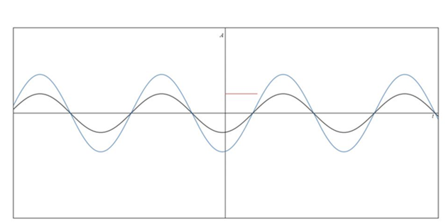
- Sketch the waveform of the voltage and current.

Fig. 15.81
(a)
The Current in phasor form.
Answer to Problem 1P
The current in phasor form is
Explanation of Solution
Given:
The sinusoidal expression of current is
The resistor value is
Concept Used:
In resistive element network, the network consists of only resistor element.
Resistor does not have any phase angle. It's purely real.
In this, the network current is in phase with voltage.
Total impedance
Current:
Calculation:
In order to convert to phasor form
Conclusion:
Hence, the current in phasor form is
(b)
Voltage across resistor in phasor form.
Answer to Problem 1P
Voltage across resistor in phasor form is
Explanation of Solution
Given:
The sinusoidal expression of current is
The resistor value is
Concept Used:
In resistive element network, the network consists of only resistor element.
Resistor does not have any phase angle. It's purely real.
In this network current are in phase with voltage.
Total impedance
Current:
Calculation:
We know that voltage across resistor is given by
Conclusion:
Hence, the voltage across resistor in phasor form is
(c)
Phasor diagram of the voltage and current.
Answer to Problem 1P
Phasor diagram of the voltage and current is drawn.
Explanation of Solution
Given:
The sinusoidal expression of current is
The resistor value is
Concept Used:
In resistive element network, the network consists of only resistor element.
Resistor does not have any phase angle. It's purely real.
In this, network current are in phase with voltage.
Total impedance
Current:
Calculation:
Based on the voltage and current value which is already obtained in above part the phasor diagram is drawn. From real axis the angle value is counted.

Conclusion:
Hence, the phasor diagram of the voltage and current is drawn.
(d)
Voltage in the sinusoidal expressions.
Answer to Problem 1P
Voltage in the sinusoidal expressions is
Explanation of Solution
Given:
The sinusoidal expression of current is
The resistor value is
Concept Used:
In resistive element network, the network consists of only resistor element.
Resistor does not have any phase angle. It's purely real.
In this, the network current is in phase with voltage.
Total impedance
Current:
Calculation:
In order to convert to sinusoidal form,
Conclusion:
Hence, voltage in the sinusoidal expressions is
(e)
Waveform of the voltage and current.
Answer to Problem 1P
Waveform of the voltage and current is drawn.
Explanation of Solution
Given:
The sinusoidal expression of current is
The resistor value is
Concept Used:
In resistive element network, the network consists of only resistor element.
Resistor does not have any phase angle. It's purely real.
In this, the network current is in phase with voltage.
Total impedance
Current:
Calculation:
Based on the voltage and current value which is already obtained in the above part, the waveform diagram is drawn. Here, A stands for amplitude.

Conclusion:
Hence, waveform of the voltage and current is drawn.
Want to see more full solutions like this?
Chapter 15 Solutions
Introductory Circuit Analysis (13th Edition)
Additional Engineering Textbook Solutions
ELECTRICITY FOR TRADES (LOOSELEAF)
Programmable Logic Controllers
Electronics Fundamentals: Circuits, Devices & Applications
Engineering Electromagnetics
Electric Circuits. (11th Edition)
Principles Of Electric Circuits


- The voltage phasor is Vs = 260 ∠15° V and the total impedance of the circuit is 15+j25 Ω . Calculate the magnitude of the phasor Is. enter your answer in A and round to two decimal places.arrow_forwardA JFET has a value of gmo = 4000 μS. Determine the value of gm at VGS = – 3V. Given that VGS (off) = – 8V.arrow_forwardConvert the following instantaneous currents to phasors, using cos(t) as the reference. Give your answers in both rectangular and polar form. (a) i(t)=5002cos(t30) (b) i(t)=4sin(t+30) (c) i(t)=5cos(t15)+42sin(t+30)arrow_forward
- Solve the following for ALL circuits. Show the summary of your answers at the end of each problem. All answers should be in polar form! a. Total Current b. Individual Currents c. Individual Voltages d. True/Real power e. Reactive power f. Apparent power 1. Circuit 1 (freq=200 Hz) 10 K www 10 COSwt 100 100 LA HE 10 pFarrow_forwardAn alternating voltage is given by v = 261.03cos341t V. Find the frequency Round your answer to 2 decimal places. Add your answerarrow_forwardPractice Exercise 1.1 Answer the following accordingly: 1. (3-j4) + (10244) then convert to rectangular form 2. (22000+j13)/(32-17) then convert to rectangular form 3. Convert 95-j12 to polar formarrow_forward
- 16. Determine the following from the given R-L-C series circuit: i) Impedance Z ii) Current i iii) Voltage across resistance VŔ iv) Voltage across inductance V₁ Pe 70.7 sin af v) Voltage across capacitance Ve vi) Total power delivered vii) Power factor R-30 W X₁ = 701 X₁ = 30 X 000 Karrow_forwardQUESTION 3 An inductor, a capacitor, and a resistor are connected in parallel with a function generator. The inductor draws 100mA RMS, the capacitor draws 150mA RMS, and the resistor draws 200mA RMS. Find the magnitude of the total current. O 450mA RMS O 544mA RMS O 352mA RMS O 206mA RMSarrow_forwardA three phase load is connected in star and connected to a supply of 400 V, 3 Φ 50 Hz. A 250 mH inductor is connected in series with a 20ohm resistor in each phase of the load. So find (1) Line voltage (2) Phase voltage (3) Phase current (4) Line current (5) Power factor (6) Active power (7) Reactive power (8) Apparent power.arrow_forward
 Power System Analysis and Design (MindTap Course ...Electrical EngineeringISBN:9781305632134Author:J. Duncan Glover, Thomas Overbye, Mulukutla S. SarmaPublisher:Cengage Learning