
Videos
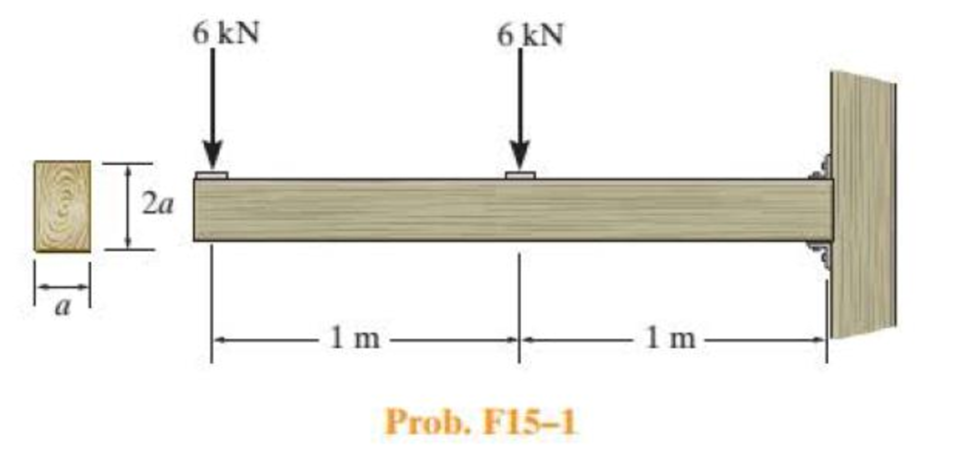
Determine the minimum dimension a to the nearest mm of the beam’s cross section to safely support the load. The wood has an allowable normal stress of σallow = 10 MPa and an allowable shear stress of τallow = 1 MPa.
Find the minimum dimension a to the nearest beam cross section.
Answer to Problem 1FP
The minimum dimension a to the nearest beam cross section is
Explanation of Solution
Given information:
The allowable bending stress is 10 MPa.
The allowable shear stress is 1 MPa.
The width of the cross section is a.
The depth of the cross section is 2a.
Calculation:
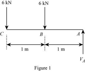
Sketch the free body diagram of beam as shown in Figure 1.
Consider a section,
Apply the equilibrium condition along y –direction.
Determine the bending moment at point A.
Calculate the moment of inertia (I) using the relation.
Here, b is the width of the section and d is the depth of the section.
Substitute a for b and 2a for d.
Calculate the dimension (a) value using the relation:
Here,
Substitute
Use,
Hence, the minimum dimension a to the nearest beam cross section is
Find the value of I using the relation:
Substitute 140 mm for a.
Find the value of
Here, A is the area of the cross section and y is the centroid of area.
Substitute
Check:
Calculate the
Here
Substitute
Hence it is OK.
Want to see more full solutions like this?
Chapter 15 Solutions
Statics and Mechanics of Materials (5th Edition)


- Determine the shear stress (in Mpa) in the 23.5-mm-diameter pin at A that support the beam if P = 28.36 kN, a = 2.25 m, and b = 6.56 m.arrow_forwardbeam is supported by a roller and a hinge at its extremities. The 2 kN/m is loaded entirely on its 4 m length while 5 kN concentrated load is positioned 2 m from the left end of this beam. If the beam is 80 mm wide, determine the minimum height of the beam if the flexural stress is not to exceed 10 MPa.arrow_forwardThe double-web girder is constructed from two plywood sheets that are secured to wood members at its top and bottom. The allowable bending stress for the wood is σallow = 8 ksi and the allowable shear stress is τallow = 3 ksi. The fasteners are spaced s = 6 in. and each fastener can support 400 lb in single shear. Determine the maximum load P that can be applied to the beam.arrow_forward
- The wood has an allowable normal stress of σallow = 15 MPa and an allowable shear stress ofτallowt = 1.33 MPa . Part A Determine the minimum dimension hh of the beam's cross section to safely support the load.arrow_forwardThe beam is constructed from three plastic strips. If the glue can support a shear stress of tallow = 8 kPa, determine the largest magnitude of the loads P that the beam can support.arrow_forwardDetermine the maximum shear force V that the strut can support if the allowable shear stress for the material is tallow = 40 MPa.arrow_forward
- The simply supported beam is built up from three boards by nailing them together as A, В shown. Determine the L1 L2 maximum allowable bf spacing s of the nails to support that load, if each nail can resist a tf tw shear force of V kN. hw tf P=17KN V=2kN L1=3.1m L2=2.5m bf=120mm tf=20mm hw=270mm tw=15mmarrow_forwardIf the beam is made of material having an allowable tensile and compressive stress of (sallow)t = 125 MPa and (sallow)c = 150 MPa, respectively, determine the maximum moment M that can be applied to the beam.arrow_forward20 mm 20 mm 4. The simply supported beam on the right is built up from three boards by nailing them together as shown. If P = 12 kN, determine the maximum allowable spacing s of the nails to support the load, if each nail can resist a shear force of 1.5 kN. 1 m m B 100 mm 25 mm- 25 mm 200 mm 25 mmarrow_forward
- The tension member is fastened together using two bolts, one on each side of the member as shown. Each bolt has a diameter of 0.3 in. Determine the maximum load P that can be applied to the member if the allowable shearstress for the bolts is tallow = 12 ksi and the allowable average normal stress is sallow = 20 ksi.arrow_forwardThe rigid beam is supported at its ends by two A-36 steel tie rods. The rods have diameters dAB = 0.5 in. and dCD = 0.3 in. If the allowable stress for the steel is sallow = 16.2 ksi, determine the largest intensity of the distributed load w and its length x on the beam so that the beam remains in the horizontal position when it is loaded.arrow_forwardThe pin is used to connect the three links together. Due to wear, the load is distributed over the top and bottom of the pin as shown on the free-body diagram. If the diameter of the pin is 0.40 in., determine the maximum bending stress on the cross-sectional area at the center section a–a. For the solution it is first necessary to determine the load intensities w1 and w2.arrow_forward
 Elements Of ElectromagneticsMechanical EngineeringISBN:9780190698614Author:Sadiku, Matthew N. O.Publisher:Oxford University Press
 Mechanics of Materials (10th Edition)Mechanical EngineeringISBN:9780134319650Author:Russell C. HibbelerPublisher:PEARSON
 Thermodynamics: An Engineering ApproachMechanical EngineeringISBN:9781259822674Author:Yunus A. Cengel Dr., Michael A. BolesPublisher:McGraw-Hill Education
 Control Systems EngineeringMechanical EngineeringISBN:9781118170519Author:Norman S. NisePublisher:WILEY
 Mechanics of Materials (MindTap Course List)Mechanical EngineeringISBN:9781337093347Author:Barry J. Goodno, James M. GerePublisher:Cengage Learning
 Engineering Mechanics: StaticsMechanical EngineeringISBN:9781118807330Author:James L. Meriam, L. G. Kraige, J. N. BoltonPublisher:WILEY