
Concept explainers
Videos
Solve Prob. 16.137 when
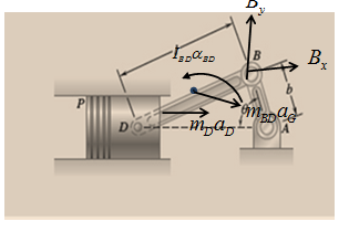
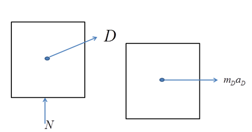
The forces exerted on the connecting rod at points B and D.
Explanation of Solution
Given information:
Connecting rod length,
Crank length
Rod mass,
Position vector,
Points D and A horizontal distance,
Position vector
Crank angular velocity in the form of vector,
Point B velocity,
Point B angular velocity in the form of vector is
Point D velocity is given by,
Compare j terms from equation A,
Compare i terms from equation A,
Crank AB angular acceleration is zero i.e.
Vector form of point B relative angular acceleration is
Vector form of point D acceleration is
Point B acceleration,
Point D acceleration,
Here,
Compare j terms in equation B,
Vector form of angular acceleration of connecting rod BD is
Compare i terms in equation B,
Vector form of acceleration of point D is
Pont G acceleration,
Here,
Point G inertial force,
Here,
Force horizontal component from figure 2,
Here,
Connected rod BD moment of inertia,
Moment at B from figure 2,
Here,
Compare K terms from equation C,
Force vertical component from figure 2,
Point B resultant reaction,
Here,
Resultant angle,
The force exerted at point B is
Forces along connecting rod from figure 3,
Hence, piston exerts force in rod which is
Point D resultant reaction,
Resultant angle,
The force exerted at point D is
Conclusion:
The force exerted at point B is
The force exerted at point D is
Want to see more full solutions like this?
Chapter 16 Solutions
Vector Mechanics For Engineers


- Gear A weighs 1.4 lb and has a radius of gyration of 1.2 in.; gear B weighs 5.2 lb and has a radius of gyration of 2.8 in.; gear C weighs 10.7 lb and has a radius of gyration of 4.4 in. Knowing a couple M of constant magnitude of 39 lb.in. is applied to gear A, determine the tangential force that gear B exerts on gear C. M A 2 in. 2 in. 4 in. B 6 in.arrow_forwardGear A weighs 1.4 lb and has a radius of gyration of 1.2 in.; gear B weighs 5.2 lb and has a radius of gyration of 2.8 in.; gear C weighs 10.7 lb and has a radius of gyration of 4.4 in. Knowing a couple M of constant magnitude of 39 lb.in. is applied to gear A, determine the tangential force that gear B exerts on gear C. M 2 in. 2 in. 4 in. B 6 in. сarrow_forwardp 9:19 تيليجرام .l| 26 Feb 2021 at 9-23 PM.H... Determike Hhe magmitude ond direction 140 Sou N momen t with rapect 1.5 to Point A 30 Nm 800N De lermine the birection ond SooN the magnitude of resultant of the for 620N the forces shown fig. 3.. 420 Narrow_forward
- Problem (1) Gears A and B each have a mass of 4 kg and a radius of gyration of 75 mm about their centers, while gear C has a mass of 15 kg and a radius of gyration of 180 mm about its center. A couple moment M = (0.20) N-m is applied to gear C. Determine the number of revolutions gears A and B experience if gear C increases its angular velocity from 25 rpm to 500 rpm. B 80 mm S0 mm 200 mmarrow_forwardIn order to unscrew the tapped faucet A, a plumber uses two pipe wrenches as shown. By exerting a 40-lb force on each wrench, at a distance of 10 in. from the axis of the pipe and in a direction perpendicular to the pipe and to the wrench, he prevents the pipe from rotating, and thus avoids loosening or further tightening the joint between the pipe and the tapped elbow C. Determine (a) the angle θ that the wrench at A should form with the vertical if elbow C is not to rotate about the vertical, (b) the force-couple system at Cequivalent to the two 40-lb forces when this condition is satisfied.arrow_forwardA shaft carries four masses A, B, C and D of magnitude 10 kg, 20 kg, 15 kg and 25 kg respectively and revolving at radii 100 mm, 50 mm, 80 mm and 120mm in planes measured from A at 100 mm, 300 mm and 500 mm. The angles between the cranks measured anticlockwise are A to B = 40°, B to C = 50° and C to D = 150°. The balancing masses are to be placed in planes X and Y. The distance between the planes A and X is 50 mm, between X and Y is 350 mm. If the balancing masses revolve at a radius of 50 mm, find the magnitude for mass on plane X (consider plane X as the refernce plane).arrow_forward
- 4 من إجمالي 4 H.W.4 In the design of a control mechanism, it is determined that rod AB transmits a 260-N force P to the crank BC. Determine the x and y scalar components of P. P= 260 N 5 12 B y 30°arrow_forwardA shaft carries four masses A, B, C and D of magnitude 10 kg, 20 kg, 15 kg and 25 kg respectively and revolving at radii 100 mm, 50mm, 80 mm and 120mm in planes measured from A at 100 mm, 300 mm and 500 mm.The angles between the cranks measured anticlockwise are A to B = 40°, B to C = 50° and C to D = 150°.The balancing masses are to be placed in planes X and Y. The distance between the planes A and X is 50 mm, between X and Y is 350mm.If the balancing masses revolve at a radius of 50 mm, find the magnitude for mass on plane X (consider plane X as the refernce plane).Select one:A.78.8 kgB.68.8 kgC.98.8 kgD.48.8 kg For the data given in Question 4, find the magnitude for mass on plane Y (consider plane X as the reference plane).Select one:A.59.1 kgB.69.1 kgC.99.1 kg D.49.1 kgarrow_forwardThe flywheel of a small punch rotates at 300 rpm. It is known that 1800 ft.1b of work must be done each time a hole is punched. It is desired that the speed of the flywheel after one punching be not less than 90 percent of the original speed of 300 rpm. (a ) Determine the required moment of inertia of the flywheel. (b) If a constant 25-1b.ft couple is applied to the shaft of the flywheel, determine the number of revolutions that must occur between each punching, knowing that the initial velocity is to be 300 rpm at the start of each punching.arrow_forward
- The flywheel of a small punch rotates at 300 rpm. It is known that 1,800 ft lb of work must be done each time a hole is punched. it is desired that the speed of the flywheel after one punching be not less that 90 percent of the original speed of 300 rpm. A. Determine the required moment of inertia of the flywheel. B. If a constant 25 lb ft couple is applied to the shaft at the flywheel, determine the number of revolutions which must occur between each punching, knowing that the initial velocity is to be 300 rpm at the start of each punching.arrow_forward3. The connecting rod of the steam engine shown schematically is assumed to be a slender uniform rod. 4 ft long weighing 322 Ib. the crank AO is 1ft long and rotates at a constant rate of 10 rad/s. the force on the 64.4 Ib cross-head at the given instant is 2142 Ib. neglecting friction. Determine the normal force on the crosshead and the horizontal and vertical components at crank pin force at A. А 45deg Вarrow_forwardThe uniform L-shaped bar pivots freely at point P of the slider, which moves along the horizontal rod. Determine the steady- state value of the angle 8 if (a) a = 0 and (b) a = 0.62 g. For what value of a would the steady-state value of 8 be zero? b 2.9 barrow_forward
 Elements Of ElectromagneticsMechanical EngineeringISBN:9780190698614Author:Sadiku, Matthew N. O.Publisher:Oxford University Press
 Mechanics of Materials (10th Edition)Mechanical EngineeringISBN:9780134319650Author:Russell C. HibbelerPublisher:PEARSON
 Thermodynamics: An Engineering ApproachMechanical EngineeringISBN:9781259822674Author:Yunus A. Cengel Dr., Michael A. BolesPublisher:McGraw-Hill Education
 Control Systems EngineeringMechanical EngineeringISBN:9781118170519Author:Norman S. NisePublisher:WILEY
 Mechanics of Materials (MindTap Course List)Mechanical EngineeringISBN:9781337093347Author:Barry J. Goodno, James M. GerePublisher:Cengage Learning
 Engineering Mechanics: StaticsMechanical EngineeringISBN:9781118807330Author:James L. Meriam, L. G. Kraige, J. N. BoltonPublisher:WILEY