
Concept explainers
Videos
Two rotating rods in the vertical plane are connected by a slider block P of negligible mass. The rod attached at A has a mass of 0.8 kg and a length of 160 mm. Rod BP has a mass of 1 kg and is 200 mm long and the friction between block P and AE is negligible. The motion of the system is controlled by a couple M applied to bar BP. Knowing that at the instant shown rod BP has an angular velocity of 20 rad/s clockwise and an angular acceleration of 80 rad/s2 clockwise, determine (a) the couple M, (b) the components of the force exerted on AE by block P.
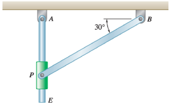
Fig. P16.141 and Fig. P16.142
(a)
Find the value of couple M.
Answer to Problem 16.142P
The value of couple M is
Explanation of Solution
Given information:
The mass of the rod AE is
The mass of the rod BP is
The length of the rod AE is
The length of the rod BP is
The angular velocity is
The angular acceleration is
Calculation:
Consider the acceleration due to gravity as
Calculate the position vector
The position of P with respect to A.
The position of P with respect to B.
The position of P with respect to E.
The angular velocity of rod BP in vector form is
The angular acceleration of rod BP in vector form is
Calculate the velocity of rod BP
Substitute
Consider the relative angular velocity of rod AE as
Calculate the velocity of point P
Substitute
Resolving i and j components as shown below.
Calculate the acceleration of rod BP
Substitute
Calculate the acceleration of point P with respect to point E
Substitute
Calculate the acceleration of point P
Substitute
Resolving i and j components as shown below.
Calculate the weight of
For rod AE.
Substitute
For rod BP.
Substitute
Calculate the mass moment of inertia
For rod AE.
Substitute
For rod BP.
Substitute
Calculate the position vector
The position of mass center G with respect to the rod AE.
The position of mass center H with respect to the rod BP.
Calculate the acceleration of point G
Substitute
Calculate the acceleration of point H
Substitute
Calculate the inertial terms of the mass center
For rod AE.
For rod BP.
Calculate the effective couples at mass center
For rod AE.
For rod BP.
Sketch the Free Body Diagram of rod AE as shown in Figure 1.
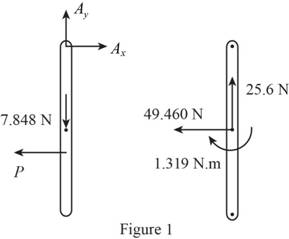
Refer to Figure 1.
Apply the Equilibrium of moment about A as shown below.
Sketch the Free Body Diagram of rod BP as shown in Figure 2.
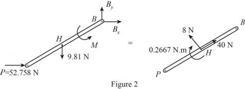
Refer to Figure 2.
Apply the Equilibrium of moment about A as shown below.
Hence, the couple M is
(b)
Find the components of the force exerted on AE by block.
Answer to Problem 16.142P
The components of the force exerted on AE by block is
Explanation of Solution
Given information:
The mass of the rod AE is
The mass of the rod BP is
The length of the rod AE is
The length of the rod BP is
The angular velocity is
The angular acceleration is
Calculation:
Refer to part (a).
The components of the force exerted on AE by block
Therefore, the components of the force exerted on AE by block is
Want to see more full solutions like this?
Chapter 16 Solutions
Vector Mechanics for Engineers: Statics and Dynamics
Additional Engineering Textbook Solutions
Introduction to Heat Transfer
INTERNATIONAL EDITION---Engineering Mechanics: Statics, 14th edition (SI unit)
Thermodynamics: An Engineering Approach
Mechanics of Materials (10th Edition)
Thermodynamics: An Engineering Approach
Vector Mechanics for Engineers: Statics, 11th Edition


- The double pulley shown has a weight of 32.5 lb and a centroidal radius of gyration of 6.0 in. Cylinder A (35.0 lb) and block B (18 lb) are attached to cords that wrap around pulleys in the manner shown. The coefficient of kinetic friction between block B and the surface is 0.25. Knowing that the system is released from rest at the position shown (h = 3 ft), determine the total distance that block B moves before coming to rest. 6 in. A h 10 in. Barrow_forwardThe mechanism shown is one of two identical mechanisms attached to the two sides of a 200-lb uniform rectangular door. Edge ABC of the door is guided by wheels of negligible mass that roll in horizontal and vertical tracks. A spring with a constant of k = 40 lb/ft is attached to wheel B. Knowing that the door is released from rest in the position 0= 30° with the spring unstretched, determine the velocity of wheel A just as the door reaches the vertical position.arrow_forwardThe mechanism shown is one of two identical mechanisms attached to the two sides of a 185-lb uniform rectangular door. Edge ABC of the door is guided by wheels of negligible mass that roll in horizontal and vertical tracks. A spring of constant k is attached to wheel B in such a way that its tension is zero when e = 30°. Knowing that the door is released from rest in the position e = 45° and reaches the vertical position with an angular velocity of 0.6 rad/s, determine the spring constant k. 5 ft C 5 ft The spring constant is 58.72 Ib/ft.arrow_forward
- The 10-in.-radius brake drum is attached to a larger flywheel which is not shown. The total mass moment of inertia of the flywheel and drum is 22 lb ⋅ ft ⋅ s 2 and the coefficient of kinetic friction between the drum and the brake shoe is 0.41. Knowing that the initial angular velocity is 255 rpm clockwise, determine the force which must be exerted by the hydraulic cylinder at point B if the system is to stop in 85 revolutions. DO NOT ROUND OFF IN THE SOLUTION. ROUND OFF ONLY THE FINAL ANSWERarrow_forwardA 48-kg advertising panel of length 2a = 2.4 m and width 2b = 1.6 m is kept rotating at a constant rate w1 about its horizontal axis by a small electric motor attached at A to frame ACB. This frame itself is kept rotating at a constant rate w2 about a vertical axis by a second motor attached at C to the column CD. Knowing that the panel and the frame complete a full revolution in 6 s and 12 s, respectively, express, as a function of the angle 0, the dynamic reaction exerted on column CD by its support at D.arrow_forwardThe 200-mm-radius brake drum is attached to a larger Bywheel. The total mass moment of inertia of the flywheel and drum is 19 kg. and the coefficient of kinetic friction between the drum and the brake shoe is 035, Knowing that the initial angular velocity of the flywheel is 180 rpm clockwise, determine the vertical force P that must be applied to the pedal C if the system is to stop in 100 revolutions. 150 mm 250 mm B ne: P= 172.88 N C 375 mm 200 mmarrow_forward
- The 10-in.-radius brake drum is attached to a larger flywheel which is not shown. The total mass moment of inertia of the flywheel and drum is 22 lb ⋅ ft ⋅ s 2 and the coefficient of kinetic friction between the drum and the brake shoe is 0.41. Knowing that the initial angular velocity is 255 rpm clockwise, determine the force which must be exerted by the hydraulic cylinder at point B if the system is to stop in 85 revolutions.arrow_forwardA garage door is mounted on an overhead rail. The wheels at A and B have rusted so that they do not roll, but rather slide along the track. The coefficient of kinetic friction is 0.55. The distance between the wheels is 2.00 m, and each is 0.50m from the vertical sides of the door. The door is uniform and weighs 850 N. It is pushed to the left at constant speed by a horizontal force F⃗, that is applied as shown in the figure. If the distance h is 1.60 m, what is the vertical component of the force exerted on the wheel A by the track? If the distance h is 1.60 m, what is the vertical component of the force exerted on the wheel B by the track? Find the maximum value hh can have without causing one wheel to leave the track.arrow_forwardA 1.6-kg tube AB can slide freely on rod DE which in turn can rotate freely in a horizontal plane. Initially the assembly is rotating with an angular velocity of magnitude w = 5 rad/s and the tube is held in position by a cord. The moment of inertia of the rod and bracket about the vertical axis of rotation is 0.30 kg.m2 and the centroidal moment of inertia of the tube about a vertical axis is 0.0025 kg.m2If the cord suddenly breaks, determine (a) the angular velocity of the assembly after the tube has moved to end E, (b) the energy lost during the plastic impact at E.arrow_forward
- Two disks of the same material are attached to a shaft as shown. Disk A has a radius r and a thickness 2b, while disk B has a radius nr and a thickness 2b. A couple M with a constant magnitude is applied when the system is at rest and is removed after the system has executed two revolutions. Determine the value of n that results in the largest final speed for a point on the rim of disk B.arrow_forwardTwo uniform cylinders, each of mass m = 6 kg and radius r = 125 mm, are connected by a belt as shown. Knowing that at the instant shown the angular velocity of cylinder A is 30 rad/s counterclockwise, determine (a) the time required for the angular velocity of cylinder A to be reduced to 5 rad/s, (b) the tension in the portion of belt connecting the two cylinders.arrow_forwardThe 10-in.-radius brake drum is attached to a larger flywheel which is not shown. The total mass moment of inertia of the flywheel and drum is 22 lb ⋅ ft ⋅ s 2 and the coefficient of kinetic friction between the drum and the brake shoe is 0.41. Knowing that the initial angular velocity is 255 rpm clockwise, determine the force which must be exerted by the hydraulic cylinder at point B if the system is to stop in 85 revolutions. determine the force which must be exerted by the hydraulic cylinder at point B if the system is to stop in 85 revolutions. DO NOT ROUND OFF IN THE SOLUTION. ROUND OFF ONLY IN 2 DECIMAL PLACE IN THE FINAL ANSWER.arrow_forward
 Elements Of ElectromagneticsMechanical EngineeringISBN:9780190698614Author:Sadiku, Matthew N. O.Publisher:Oxford University Press
 Mechanics of Materials (10th Edition)Mechanical EngineeringISBN:9780134319650Author:Russell C. HibbelerPublisher:PEARSON
 Thermodynamics: An Engineering ApproachMechanical EngineeringISBN:9781259822674Author:Yunus A. Cengel Dr., Michael A. BolesPublisher:McGraw-Hill Education
 Control Systems EngineeringMechanical EngineeringISBN:9781118170519Author:Norman S. NisePublisher:WILEY
 Mechanics of Materials (MindTap Course List)Mechanical EngineeringISBN:9781337093347Author:Barry J. Goodno, James M. GerePublisher:Cengage Learning
 Engineering Mechanics: StaticsMechanical EngineeringISBN:9781118807330Author:James L. Meriam, L. G. Kraige, J. N. BoltonPublisher:WILEY