
Vector Mechanics for Engineers: Statics and Dynamics
12th Edition
ISBN: 9781259638091
Author: Ferdinand P. Beer, E. Russell Johnston Jr., David Mazurek, Phillip J. Cornwell, Brian Self
Publisher: McGraw-Hill Education
expand_more
expand_more
format_list_bulleted
Concept explainers
Videos
Textbook Question
Chapter 16.2, Problem 16.4CQ
A cord is attached to a spool when a force P is applied to the cord as shown. Assuming the spool rolls without slipping, what direction does the spool move for each case?
Case 1: a. left b. right c. It would not move.
Case 2: a. left b. right c. It would not move.
Case 3: a. left b. right c. It would not move.
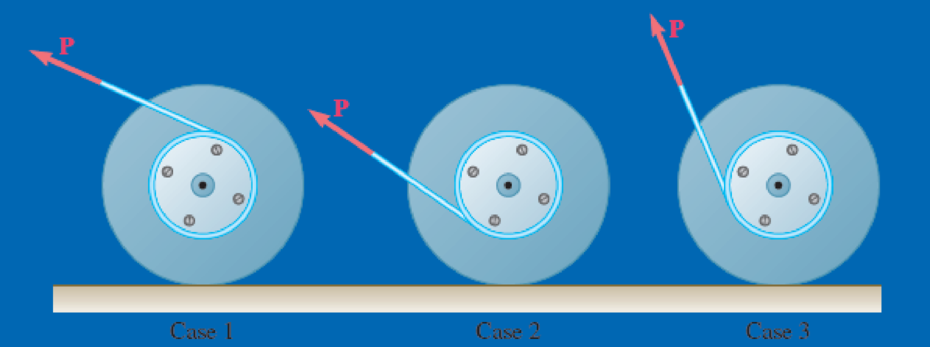
Fig. P16.CQ4 and P16.CQ5
Expert Solution & Answer
Want to see the full answer?
Check out a sample textbook solution
Students have asked these similar questions
PROBLEM 4.1
The wheel of an automobile revolves at the rate of 700 rpm. How fast does it
move in kilometre per hour, if the radius of its wheel is 250 mm.
6.09 kph
5.09 kph
1.
c. 7.09 kph
d. 8.09 kph
а.
b.
Consider the mechanism shown. Members PQ and QR are joined by a hinge at Q. End P of member PQ is pin-supported and end R of member QR is constrained to move along a horizontal surface. Member PQ rotates clockwise at a constant rate of 12 rad/s. Member QR rotates counterclockwise at a rate of 3.84 rad/s.
Which of the following gives the closest value to the magnitude of the angular acceleration of rod QR?
9.16, 6.18, 1.609, 35.2 rad/s^2?? Which of the following gives the closest value to the magnitude of the acceleration of point R?
3.13, 9.89, 10.28, 12.88 m/s^2??
Assuming that in Prob. 8.75 a right-handed thread is used on both rods A and B , determine the magnitude of the couple that must be applied to the sleeve in order to rotate it.(Reference to Problem 8.75):The ends of two fixed rods A and B are each made in the form of a single-threaded screw with a mean radius of 6 mm and pitch of 2 mm. Rod A has a right-handed thread, and rod B has a left-handed thread. The coefficient of static friction between the rods and the threaded sleeve is 0.12. Determine the magnitude of the couple that must be applied to the sleeve in order to draw the rods closer together.
Chapter 16 Solutions
Vector Mechanics for Engineers: Statics and Dynamics
Ch. 16.1 - Two pendulums, A and B, with the masses and...Ch. 16.1 - Two pendulums, A and B, with the masses and...Ch. 16.1 - Two solid cylinders, A and B, have the same mass m...Ch. 16.1 - Prob. 16.1FBPCh. 16.1 - Prob. 16.2FBPCh. 16.1 - Prob. 16.3FBPCh. 16.1 - The 400-lb crate shown is lowered by means of two...Ch. 16.1 - A 60-lb uniform thin panel is placed in a truck...Ch. 16.1 - A 60-lb uniform thin panel is placed in a truck...Ch. 16.1 - A loading car is at rest on a track forming an...
Ch. 16.1 - A 2100-lb rear-wheel-drive tractor carries a 900...Ch. 16.1 - A uniform rod BC of mass 4 kg is connected to a...Ch. 16.1 - A 2000-kg truck is being used to lift a 400-kg...Ch. 16.1 - The support bracket shown is used to transport a...Ch. 16.1 - Prob. 16.8PCh. 16.1 - A 20-kg cabinet is mounted on casters that allow...Ch. 16.1 - Solve Prob. 16.9, assuming that the casters are...Ch. 16.1 - Prob. 16.11PCh. 16.1 - Prob. 16.12PCh. 16.1 - The retractable shelf shown is supported by two...Ch. 16.1 - Bars AB and BE, each with a mass of 4 kg, are...Ch. 16.1 - At the instant shown, the tensions in the vertical...Ch. 16.1 - Three bars, each of mass 3 kg, are welded together...Ch. 16.1 - Members ACE and DCB are each 600 mm long and are...Ch. 16.1 - A prototype rotating bicycle rack is designed to...Ch. 16.1 - The control rod AC is guided by two pins that...Ch. 16.1 - The coefficients of friction between the 30-lb...Ch. 16.1 - Prob. 16.21PCh. 16.1 - Prob. 16.22PCh. 16.1 - For a rigid body in translation, show that the...Ch. 16.1 - For a rigid body in centroidal rotation, show that...Ch. 16.1 - It takes 10 min for a 2.4-Mg flywheel to coast to...Ch. 16.1 - The rotor of an electric motor has an angular...Ch. 16.1 - The 10-in.-radius brake drum is attached to a...Ch. 16.1 - The 10-in.-radius brake drum is attached to a...Ch. 16.1 - The 100-mm-radius brake drum is attached to a...Ch. 16.1 - The 180-mm-radius disk is at rest when it is...Ch. 16.1 - Solve Prob. 16.30, assuming that the direction of...Ch. 16.1 - In order to determine the mass moment of inertia...Ch. 16.1 - The flywheel shown has a radius of 20 in., a...Ch. 16.1 - Each of the double pulleys shown has a mass moment...Ch. 16.1 - Two disks A and B, of mass mA = 2 kg and mB = 4...Ch. 16.1 - Two disks A and B, of mass mA = 2 kg and mB = 4...Ch. 16.1 - Gear A weighs 1 lb and has a radius of gyration of...Ch. 16.1 - The 25-lb double pulley shown is at rest and in...Ch. 16.1 - A belt of negligible mass passes between cylinders...Ch. 16.1 - Prob. 16.40PCh. 16.1 - Disk A has a mass of 6 kg and an initial angular...Ch. 16.1 - Prob. 16.42PCh. 16.1 - Disk A has a mass mA = 4 kg, a radius rA = 300 mm,...Ch. 16.1 - Disk B is at rest when it is brought into contact...Ch. 16.1 - Prob. 16.45PCh. 16.1 - Prob. 16.46PCh. 16.1 - For a rigid body in plane motion, show that the...Ch. 16.1 - A uniform slender rod AB rests on a frictionless...Ch. 16.1 - Prob. 16.49PCh. 16.1 - Prob. 16.50PCh. 16.1 - Prob. 16.51PCh. 16.1 - A 250-lb satellite has a radius of gyration of 24...Ch. 16.1 - A rectangular plate of mass 5 kg is suspended from...Ch. 16.1 - Prob. 16.54PCh. 16.1 - A drum with a 200-mm radius is attached to a disk...Ch. 16.1 - A drum with a 200-mm radius is attached to a disk...Ch. 16.1 - The 12-lb uniform disk shown has a radius of r =...Ch. 16.1 - Prob. 16.58PCh. 16.1 - Prob. 16.59PCh. 16.1 - 16.60 and 16.61The 400-lb crate shown is lowered...Ch. 16.1 - Prob. 16.61PCh. 16.1 - Two uniform cylinders, each of weight W = 14 lb...Ch. 16.1 - Prob. 16.63PCh. 16.1 - Prob. 16.64PCh. 16.1 - A uniform slender bar AB with a mass m is...Ch. 16.1 - Prob. 16.66PCh. 16.1 - 16.66 through 16.68A thin plate of the shape...Ch. 16.1 - 16.66 through 16.68A thin plate of the shape...Ch. 16.1 - A sphere of radius r and mass m is projected along...Ch. 16.1 - Solve Prob. 16.69, assuming that the sphere is...Ch. 16.1 - A bowler projects an 8-in.-diameter ball weighing...Ch. 16.1 - Prob. 16.72PCh. 16.1 - A uniform sphere of radius r and mass m is placed...Ch. 16.1 - A sphere of radius r and mass m has a linear...Ch. 16.2 - A cord is attached to a spool when a force P is...Ch. 16.2 - Prob. 16.5CQCh. 16.2 - Prob. 16.6CQCh. 16.2 - Prob. 16.7CQCh. 16.2 - Prob. 16.5FBPCh. 16.2 - Two identical 4-lb slender rods AB and BC are...Ch. 16.2 - Prob. 16.7FBPCh. 16.2 - Prob. 16.8FBPCh. 16.2 - Show that the couple I of Fig. 16.15 can be...Ch. 16.2 - A uniform slender rod of length L = 900 mm and...Ch. 16.2 - A crate of mass 80 kg is held in the position...Ch. 16.2 - A uniform slender rod of length L = 36 in. and...Ch. 16.2 - In Prob. 16.78, determine (a) the distance h for...Ch. 16.2 - An athlete performs a leg extension on a machine...Ch. 16.2 - Prob. 16.81PCh. 16.2 - A turbine disk weighing 50 lb rotates at a...Ch. 16.2 - The 80-lb tailgate of a car is supported by the...Ch. 16.2 - A uniform rod of length L and mass m is supported...Ch. 16.2 - Three stage lights are mounted on a pipe fixture...Ch. 16.2 - An adapted launcher uses a torsional spring about...Ch. 16.2 - A 4-kg slender rod is welded to the edge of a 3-kg...Ch. 16.2 - Prob. 16.88PCh. 16.2 - The object ABC consists of two slender rods welded...Ch. 16.2 - A 3.5-kg slender rod AB and a 2-kg slender rod BC...Ch. 16.2 - A 9-kg uniform disk is attached to the 5-kg...Ch. 16.2 - Derive the equation MC=IC for the rolling disk of...Ch. 16.2 - Prob. 16.93PCh. 16.2 - Prob. 16.94PCh. 16.2 - Prob. 16.95PCh. 16.2 - Prob. 16.96PCh. 16.2 - A 40-kg flywheel of radius R = 0.5 m is rigidly...Ch. 16.2 - Prob. 16.98PCh. 16.2 - 16.98 through 16.101A drum of 80-mm radius is...Ch. 16.2 - 16.98 through 16.101A drum of 80-mm radius is...Ch. 16.2 - 16.98 through 16.101A drum of 80-mm radius is...Ch. 16.2 - 16.102 through 16.105A drum of 4-in. radius is...Ch. 16.2 - 16.102 through 16.105A drum of 4-in. radius is...Ch. 16.2 - 16.102 through 16.105A drum of 4-in. radius is...Ch. 16.2 - 16.102 through 16.105A drum of 4-in. radius is...Ch. 16.2 - 16.106 and 16.107A 12-in.-radius cylinder of...Ch. 16.2 - 16.106 and 16.107A 12-in.-radius cylinder of...Ch. 16.2 - Gear C has a mass of 5 kg and a centroidal radius...Ch. 16.2 - Two uniform disks A and B, each with a mass of 2...Ch. 16.2 - A single-axis personal transport device starts...Ch. 16.2 - A hemisphere of weight W and radius r is released...Ch. 16.2 - A hemisphere of weight W and radius r is released...Ch. 16.2 - The center of gravity G of a 1.5-kg unbalanced...Ch. 16.2 - A small clamp of mass mB is attached at B to a...Ch. 16.2 - Prob. 16.115PCh. 16.2 - A 4-lb bar is attached to a 10-lb uniform cylinder...Ch. 16.2 - The uniform rod AB with a mass m and a length of...Ch. 16.2 - Prob. 16.118PCh. 16.2 - Prob. 16.119PCh. 16.2 - Prob. 16.120PCh. 16.2 - End A of the 6-kg uniform rod AB rests on the...Ch. 16.2 - End A of the 6-kg uniform rod AB rests on the...Ch. 16.2 - End A of the 8-kg uniform rod AB is attached to a...Ch. 16.2 - The 4-kg uniform rod ABD is attached to the crank...Ch. 16.2 - The 3-lb uniform rod BD is connected to crank AB...Ch. 16.2 - The 3-lb uniform rod BD is connected to crank AB...Ch. 16.2 - The test rig shown was developed to perform...Ch. 16.2 - Solve Prob. 16.127 for = 90. 16.127The test rig...Ch. 16.2 - The 4-kg uniform slender bar BD is attached to bar...Ch. 16.2 - The motion of the uniform slender rod of length L...Ch. 16.2 - At the instant shown, the 20-ft-long, uniform...Ch. 16.2 - A driver starts his car with the door on the...Ch. 16.2 - Prob. 16.133PCh. 16.2 - The hatchback of a car is positioned as shown to...Ch. 16.2 - The 6-kg rod BC connects a 10-kg disk centered at...Ch. 16.2 - Prob. 16.136PCh. 16.2 - In the engine system shown, l = 250 mm and b = 100...Ch. 16.2 - Solve Prob. 16.137 when = 90. 16.137In the engine...Ch. 16.2 - The 4-lb uniform slender rod AB, the 8-lb uniform...Ch. 16.2 - The 4-lb uniform slender rod AB, the 8-lb uniform...Ch. 16.2 - Two rotating rods in the vertical plane are...Ch. 16.2 - Two rotating rods in the vertical plane are...Ch. 16.2 - Two disks, each with a mass m and a radius r, are...Ch. 16.2 - A uniform slender bar AB of mass m is suspended as...Ch. 16.2 - A uniform rod AB, of mass 15 kg and length 1 m, is...Ch. 16.2 - The uniform slender 2-kg bar BD is attached to the...Ch. 16.2 - Prob. 16.147PCh. 16.2 - Prob. 16.148PCh. 16.2 - Prob. 16.149PCh. 16.2 - Prob. 16.150PCh. 16.2 - (a) Determine the magnitude and the location of...Ch. 16.2 - Prob. 16.152PCh. 16 - A cyclist is riding a bicycle at a speed of 20 mph...Ch. 16 - The forklift truck shown weighs 3200 lb and is...Ch. 16 - The total mass of the Baja car and driver,...Ch. 16 - Identical cylinders of mass m and radius r are...Ch. 16 - Prob. 16.157RPCh. 16 - The uniform rod AB of weight W is released from...Ch. 16 - Prob. 16.159RPCh. 16 - Prob. 16.160RPCh. 16 - A cylinder with a circular hole is rolling without...Ch. 16 - Two 3-kg uniform bars are connected to form the...Ch. 16 - A crate of mass 80 kg is held in the position...Ch. 16 - The Geneva mechanism shown is used to provide an...
Additional Engineering Textbook Solutions
Find more solutions based on key concepts
Select a mechanical component from Part 3 of this book (roller bearings, springs, etc.), go to the Internet, an...
Shigley's Mechanical Engineering Design (McGraw-Hill Series in Mechanical Engineering)
A 20-lb force is applied to the control rod AB as shown. Knowing that the length of the rod is 9 in. and that t...
Statics and Mechanics of Materials
Locate the centroid of the area. Prob. 9-17
Engineering Mechanics: Statics
For the beam loading of Figure P334, draw the complete shearing force and bending moment diagrams, and determin...
Machine Elements in Mechanical Design (6th Edition) (What's New in Trades & Technology)
What types of polymers are most commonly blow molded?
DeGarmo's Materials and Processes in Manufacturing
Determine the length of the cantilevered beam so that the maximum bending stress in the beam is equivalent to t...
Mechanics of Materials (10th Edition)
Knowledge Booster


Learn more about
Need a deep-dive on the concept behind this application? Look no further. Learn more about this topic, mechanical-engineering and related others by exploring similar questions and additional content below.Similar questions
- Problem 18.2 As part of a school bus safety test program, school buses are being tested for potential roll-over hazards. To test the bus, it is placed on 1000-pound moveable concrete pad that rolls freely without friction. The horizontal motion of the pad is produced by a hydraulic ram which pulls the pad to left. A 5000-pound school bus is placed on the pad as shown in the figure. a) Assuming the bus does not slip on the pad, determine the minimum value of the horizontal acceleration (dv/dt) of the pad in the direction indicated that will cause the bus to tip, in ft/s². b) Determine the force, in lbf, that the ram must apply to the platform to produce the acceleration found in part (a). c) Determine the minimum static coefficient of friction between the tires and the concrete pad that is required to keep the bus from slipping on the moving pad. d = 3 ft h = 4 ft Desired direction of pad motion Hydraulic Ram h Bus Pad Ans: a) 23 ft/s² ≤ |ax| ≤ 25 ft/s² b) 4500 lbf ≤|F| ≤ 4600 lbf c)…arrow_forwardA Cord Is Attached To A Spool When A Force P Is Applied To The Cord As Shown. Assuming The Spool Rolls Without Slipping, what direction does the spool move in each case? left, right or it will not move?arrow_forwardQ.1 The dimensions and configuration of the four bar mechanism, shown in Fig. 1 are as follows : PA = 300 mm; P,B = 360 mm; AB = 360 mm, and P;P2 = 600 mm. The angle AP;P2 = 60°. The crank PA has an angular velocity of 10 rad/s, anticlockwise. Determine the angular velocities and angular accelerations of PB, and AB and the velocity and acceleration of the joint B 360 mm A 360 mm 60° T ケ P, TTTTI P2 600 mm Fig. 1 300 mmarrow_forward
- Q: As part of a test, the two aircraft engines are revved up and the propeller pitches are adjusted so as to result in the fore and aft thrusts shown. What force F must be exerted by the ground on each of the main braked wheels at A and B to counteract the turning effect of the two propeller thrusts? Neglect any effects of the nose wheel C, which is turned 90° and unbraked. 500 lb 8' 14" 500 lbarrow_forward1. A thin pole of length L = 3 m and mass 6 kg is being raised by a rope of tension 80 Newtons as shown. The left end of the pole can rotate about a pivot attached to the wall. Determine the magnitude and direction of the angular acceleration of the pole. The general steps in applying the rotational 2nd law are given below. a. Draw an extended free body diagram showing the forces on the rod and where they act. • The weight acts at the center of mass. • There must be a force at the pivot that holds that end in place. b. Determine the torque generated by each force on your FBD. Sum the torques to get the left-hand side (LHS) of the rotational 2nd law. C. Determine the moment of inertia of the pole. FBD 30° T d. Apply the rotational 2nd law to determine the magnitude and direction of angular acceleration of the pole.arrow_forwardA shaft turning at a uniform speed carries two uniform discs A and B of masses 10kg and 8kg respectively. The centres of the mass of the discs are each 2.5mm from the axis of rotation. The radii to the centres of mass are at right angles. The shaft is carried in bearings C and D between A and B such that AC = 0.3m, AD = 0.9m and AB = 1.2m. It is required to make dynamic loading on the bearings equal and a minimum for any given shaft speed by adding a mass at a radius 25mm in a plane E. Determine: The dynamic loading on each bearing when the mass in plane E has been attached and the shaft rotates at 200 rev/min. For the bearing loads in the opposite direction determine all the unknown values. For the bearing loads in the same direction, show the diagrams and equations only to use for a possible solution. PS – Use graphical methods to solve the balancing problemarrow_forward
- A shaft turning at a uniform speed carries two uniform discs A and B of masses 10kg and 8kg respectively. The centres of the mass of the discs are each 2.5mm from the axis of rotation. The radii to the centres of mass are at right angles. The shaft is carried in bearings C and D between A and B such that AC = 0.3m, AD = 0.9m and AB = 1.2m. It is required to make dynamic loading on the bearings equal and a minimum for any given shaft speed by adding a mass at a radius 25mm in a plane E. Determine: The magnitude of the mass in plane E and its angular position relative to the mass in plane A The distance of the plane E from plane A PS – Use graphical methods to solve the balancing problemarrow_forwardA shaft turning at a uniform speed carries two uniform discs A and B of masses 10kg and 8kg respectively. The centres of the mass of the discs are each 2.5mm from the axis of rotation. The radii to the centres of mass are at right angles. The shaft is carried in bearings C and D between A and B such that AC = 0.3m, AD = 0.9m and AB = 1.2m. It is required to make dynamic loading on the bearings equal and a minimum for any given shaft speed by adding a mass at a radius 25mm in a plane E. Determine: (a) The magnitude of the mass in plane E and its angular position relative to the mass in plane A (b) The distance of the plane E from plane A (c) The dynamic loading on each bearing when the mass in plane E has been attached and the shaft rotates at 200 rev/min. For the bearing loads in the opposite direction determine all the unknown values. For the bearing loads in the same direction, show the diagrams and equations only to use for a possible solution.arrow_forwardA shaft turning at a uniform speed carries two uniform discs A and B of masses 10kg and 8kg respectively. The centres of the mass of the discs are each 2.5mm from the axis of rotation. The radii to the centres of mass are at right angles. The shaft is carried in bearings C and D between A and B such that AC = 0.3m, AD = 0.9m and AB = 1.2m. It is required to make dynamic loading on the bearings equal and a minimum for any given shaft speed by adding a mass at a radius 25mm in a plane E. Determine: (a) The magnitude of the mass in plane E and its angular position relative to the mass in plane (b) The distance of the plane E from plane A (c) The dynamic loading on each bearing when the mass in plane E has been attached and the shaft rotates at 200 rev/min. For the bearing loads in the opposite direction determine all the unknown values. For the bearing loads in the same direction, show the diagrams and equations only to use for a possible solution. PS - Use graphical methods to solve the…arrow_forward
- A shaft turning at a uniform speed carries two uniform discs A and B of masses 10kg and 8kg respectively. The centres of the mass of the discs are each 2.5mm from the axis of rotation. The radii to the centres of mass are at right angles. The shaft is carried in bearings C and D between A and B such that AC = 0.3m, AD = 0.9m and AB = 1.2m. It is required to make dynamic loading on the bearings equal and a minimum for any given shaft speed by adding a mass at a radius 25mm in a plane E. Determine: The magnitude of the mass in plane E and its angular position relative to the mass in plane A The distance of the plane E from plane A The dynamic loading on each bearing when the mass in plane E has been attached and the shaft rotates at 200 rev/min. For the bearing loads in the opposite direction determine all the unknown values. For the bearing loads in the same direction, show the diagrams and equations only to use for a possible solution. PS – Use graphical methods to solve the…arrow_forwardA shaft turning at a uniform speed carries two uniform discs A and B of masses 10kg and 8kg respectively. The centres of the mass of the discs are each 2.5mm from the axis of rotation. The radii to the centres of mass are at right angles. The shaft is carried in bearings C and D between A and B such that AC = 0.3m, AD = 0.9m and AB = 1.2m. It is required to make dynamic loading on the bearings equal and a minimum for any given shaft speed by adding a mass at a radius 25mm in a plane E. USING THE METHOD OF DRAWING m*r and m*r*l diagram Determine: The magnitude of the mass in plane E and its angular position relative to the mass in plane A The distance of the plane E from plane A The dynamic loading on each bearing when the mass in plane E has been attached and the shaft rotates at 200 rev/min. For the bearing loads in the opposite direction determine all the unknown values. For the bearing loads in the same direction, show the diagrams and equations only to use for a possible…arrow_forward16.77 A uniform slender rod of weight 0.24 lb/ft is used to form the assembly shown. The assembly rotates clockwise at a constant rate of under the combined effect of gravity and the couple M which varies in magnitude and sense. Determine the magnitude and sense of the couple M and the reaction at point A for (a) 0 = 90°, (b) 0 = 180°. 120 rpm 8 in A Fig. P16.77 Marrow_forward
arrow_back_ios
SEE MORE QUESTIONS
arrow_forward_ios
Recommended textbooks for you
 Elements Of ElectromagneticsMechanical EngineeringISBN:9780190698614Author:Sadiku, Matthew N. O.Publisher:Oxford University Press
 Mechanics of Materials (10th Edition)Mechanical EngineeringISBN:9780134319650Author:Russell C. HibbelerPublisher:PEARSON
 Thermodynamics: An Engineering ApproachMechanical EngineeringISBN:9781259822674Author:Yunus A. Cengel Dr., Michael A. BolesPublisher:McGraw-Hill Education
 Control Systems EngineeringMechanical EngineeringISBN:9781118170519Author:Norman S. NisePublisher:WILEY
 Mechanics of Materials (MindTap Course List)Mechanical EngineeringISBN:9781337093347Author:Barry J. Goodno, James M. GerePublisher:Cengage Learning
 Engineering Mechanics: StaticsMechanical EngineeringISBN:9781118807330Author:James L. Meriam, L. G. Kraige, J. N. BoltonPublisher:WILEY
Elements Of Electromagnetics
Mechanical Engineering
ISBN:9780190698614
Author:Sadiku, Matthew N. O.
Publisher:Oxford University Press
Mechanics of Materials (10th Edition)
Mechanical Engineering
ISBN:9780134319650
Author:Russell C. Hibbeler
Publisher:PEARSON
Thermodynamics: An Engineering Approach
Mechanical Engineering
ISBN:9781259822674
Author:Yunus A. Cengel Dr., Michael A. Boles
Publisher:McGraw-Hill Education
Control Systems Engineering
Mechanical Engineering
ISBN:9781118170519
Author:Norman S. Nise
Publisher:WILEY
Mechanics of Materials (MindTap Course List)
Mechanical Engineering
ISBN:9781337093347
Author:Barry J. Goodno, James M. Gere
Publisher:Cengage Learning
Engineering Mechanics: Statics
Mechanical Engineering
ISBN:9781118807330
Author:James L. Meriam, L. G. Kraige, J. N. Bolton
Publisher:WILEY
Mechanical Design (Machine Design) Clutches, Brakes and Flywheels Intro (S20 ME470 Class 15); Author: Professor Ted Diehl;https://www.youtube.com/watch?v=eMvbePrsT34;License: Standard Youtube License