
Concept explainers
Videos
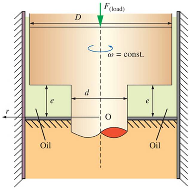
The rotating parts of a hydroelectric power plant having power capacity W have a rotational synchronous speed it. The weight of the rotating parts (the hydroturbine and its electric generator) is supported in a thrust bearing having amulet form between D and d diameters as sketched the thrust hearing is operated with a very thin oil film of thickness e and dynamic viscosity. It is armed that the oil is a Newtonian fluid and the velocity is approximated as linear in the hearing. Calculate the ratio of lost power in the thrust heating to the produced power in the hydraulic power plant. Use
The ratio of lost power in the thrust bearing.
Answer to Problem 127P
The ratio of lost power in the thrust bearing is
Explanation of Solution
Given information:
The larger diameter of the bearing is
Write the expression for the area in differential form.
Here, the area of the plant is
Write the expression for the radius of the smaller bearing.
Here, the radius of the smaller bearing is
Write the expression for the radius of the larger bearing.
Here, the radius of the larger bearing is
Write the expression for the volume of the plant in differential form.
Here, the volume of the plant is
Write the expression for the angular velocity.
Here, the speed of the plant is
Write the expression for the shear stress due to viscosity.
Here, the shear stress due to viscosity is
Write the expression for the force due to shear stress.
Here, the force due to shear stress is
Write the expression for the power loss due to viscosity of oil.
Here, the power loss is
Write the expression for the net power produced.
Here, the net power produced is
Write the expression for the ratio of power loss.
Here, the ratio of power loss is
Calculation:
Substitute
Substitute
Substitute
Substitute
Substitute
Substitute
Integrate Equation (XIII) under the lower limit
Substitute
Integrate Equation (XIV) under the lower limit
Substitute
Substitute
Integrate Equation (XVI) under the lower limit
Substitute
Substitute
Conclusion:
The ratio of lost power in the thrust bearing is
Want to see more full solutions like this?
Chapter 2 Solutions
Fluid Mechanics: Fundamentals and Applications


- The physical model of a pipe containing water with kinematic viscosity has been built in the scale of in a laboratory. Find the ratio of velocity of water in the main pipe with kinematic viscosity of to the model. Discuss the difference in the velocities of the model and main pipe.arrow_forwardTake the densilty and pressure values at 7km, and then apply Bernoulli equation. I think this is the method to solve the problem,If there any you can proceed with that. Please do it fast ,Very urgent. Question 1: . Consider an airplane flying at a standard altitude of 7 km with a velocity of 300 m/s. At a point on the wing of the airplane, the velocity is 400 m/s. Calculate the pressure at this point.arrow_forwardThe rotating parts of a hydroelectric power plant having power capacity W . have a rotational synchronous speed n .. The weight of the rotating parts (the hydroturbine and its electric generator) is supported in a thrust bearing having annular form between D and d diameters as sketched. The thrust bearing is operated with a very thin oil film of thickness e and dynamic viscosity ? . It is assumed that the oil is a Newtonian fluid and the velocity is approximated as linear in the bearing. Calculate the ratio of lost power in the thrust bearing to the produced power in the hydraulic power plant. Use W . = 48.6 MW, ? = 0.035 Pa⋅s, n . = 500 rpm, e = 0.25 mm, D = 3.2 m, and d = 2.4 m.arrow_forward
- Asaparrow_forwardC1 (a). A lubricating oil having the dynamic viscosity of 0.056 poise and specific gravity of 1.17. Calculate (i) the density of oil in kg/m3, (ii) the weight density of oil in N/m3, (iii) the kinematic viscosity in stokes, and (iv) the specific volume in m3/kg. C1 (b). The capillary effect in a glass tube of 2.8 mm diameter, when immersed in (1) water and (2) mercury are 7.7 mm and -3.5 mm respectively. Calculate the value of surface tension in contact with air for water and mercury in N/m. Take, the contact angle for water =0° and mercury =130°. C1(a). (i).the density of oil in kg/m3 C1(a). (ii) the weight density of oil in N/m3 C1(a). (iii) the kinematic viscosity in stokes C1(a). (iv) the specific volume in m3/kg C1 (b). 1.the value of surface tension (water) in N/m C1 (b). 2. the value of surface tension (mercury) in N/marrow_forwardC1 (a). A lubricating oil having the dynamic viscosity of 0.058 poise and specific gravity of 1.11. Calculate (i) the density of oil in kg/m3, (ii) the weight density of oil in N/m3,(iii) the kinematic viscosity in stokes, and (iv) the specific volume in m³/kg. C1 (b). The capillary effect in a glass tube of 2.6 mm diameter, when immersed in (1) water and (2) mercury are 7.4 mm and -3.5 mm respectively. Calculate the value of surface tension in contact with air for water and mercury in N/m. Take, the contact angle for water =0° and mercury =130°. C1(a).(i).the density of oil in kg/m3 C1(a). (ii) the weight density of oil in N/m3 C1(a). (iii) the kinematic viscosity in stokes C1(a). (iv) the specific volume in m³/kg C1 (b). 1.the value of surface tension (water) in N/m C1 (b). 2. the value of surface tension (mercury) in N/marrow_forward
- The physical model of a pipe containing water with kinematic viscosity o = 0.804 × 10⁻⁶ ™* has been built in the scale of in a laboratory. i. Find the ratio of velocity of water in the main pipe with kinematic viscosity of 8 = 2.79 x 10⁻⁴ m? to the model. ii. Discuss the difference in the velocities of the model and main pipe.arrow_forwardis called a cone-plate viscometer A solid cone of angle 2k, base 1, and density p, is rotat- Ing with initial angular velocity my inside a conical.seat, as shown in Fig. of viscosity u. Neglecting air drag, derive an analytical ex- pression for the cone's angular velocity ) if there is no applied tongue. The device in Fig. The angle of the cone is very small, so thiat sin 0 0, and the gap is filled with the test liquid. The torque M to rotate the cone at a rate 1 is measured. Assuming a lin- ear velocity profile in the fluid film, derive an expression for tiuid viscosity u as a tumction of (M, R. S2, 0). The clearance h is filled with nil Bave C co radius a dwit) dt Fluid I manmot 1Inentia Derive an expression for the capillary height change h for a fluid of surface tension Y and contact angle 0 between two vertical parallel plates a distance W apart, as in Fig. . What will li be for water at 20°C if W = 0.5 mm? A thin plate is separated from two fixed plates by very vis- cous liquids…arrow_forwardplz help me with this one i would appreciate it if you help me now A piston with a diameter of 0.8 m and width of L=0.6 m rotates with 6 rad/s inside a cylinder that has a diameter of 1 m that filled with oil that has a viscosity of 8x10⁻³ N.s/m2 What is the shear force that acts on the circumference of the piston (N)? Assume the variation in velocity of the oil is linear.arrow_forward
- An incompressible fluid (kinematic viscosity, 7.4 x10⁻⁷ m²/s, specific gravity, 0.88) is held between two parallel plates. If the top plate is moved with a velocity of 0.5 m/s while the bottom one is held stationary, the fluid attains a linear velocity profile in the gap of 0.5 mm between these plates; the shear stress in Pascals on the surface of top plate is (a) 0.651 x 10⁻³ (c) 6.51 (b) 0.651 (d) 0.651 x 10³arrow_forwardA viscous incompressible liquid of density p and of dynamic viscosity n is carried upwards against gravity with the aid of moving side walls. This laminar flow is steady and fully developed in z-direction and there is no applied pressure gradient. The coordinate is fixed in the midway between the walls as shown below. 2d g=-gk liquid P, n x=-d x=d I. The velocity profile in z-direction is pg w(x) = (x2 – d) + U. 2n II. To be able to carry a net amount of liquid upwards, the wall velocities need to be greater than pgd²/(2n). III. If one of the walls stops, increasing the speed of the other wall to 3/2U would carry the same amount of liquid upwards. Which of the above statements are true?arrow_forwardA film of liquid with kinematic viscosity and density p spreads over a flat horizontal surface due to gravity as shown. Assume that the spread is planar in x - y plane with unit width into page. The height of the film is h(x, t) which varies in a direction and time t. The flow is incompressible and the x-velocity is u(x, y, t) which is governed by the lubrication theory due to the small thickness of the film (h < L). The pressure outside the film is uniform and atmospheric. Inside the film the pressure variation is hydrostatic in y direction. At x = 0, h = h, and h is symmetric in z (i.e., h(L,t) = h(-L, t)). The gravitational acceleration is g. x=-L hexat) ấy x u(x, y, t) = -2y(2h - y). x=L Show that +(udy) = 0 Using lubrication theory show that the velocity profile ↓g Assuming that Oh/dt = constant, use (a) and (b) results to find h(r, t) in term of ho, x, ah/ot, v, L and g.arrow_forward
 Elements Of ElectromagneticsMechanical EngineeringISBN:9780190698614Author:Sadiku, Matthew N. O.Publisher:Oxford University Press
 Mechanics of Materials (10th Edition)Mechanical EngineeringISBN:9780134319650Author:Russell C. HibbelerPublisher:PEARSON
 Thermodynamics: An Engineering ApproachMechanical EngineeringISBN:9781259822674Author:Yunus A. Cengel Dr., Michael A. BolesPublisher:McGraw-Hill Education
 Control Systems EngineeringMechanical EngineeringISBN:9781118170519Author:Norman S. NisePublisher:WILEY
 Mechanics of Materials (MindTap Course List)Mechanical EngineeringISBN:9781337093347Author:Barry J. Goodno, James M. GerePublisher:Cengage Learning
 Engineering Mechanics: StaticsMechanical EngineeringISBN:9781118807330Author:James L. Meriam, L. G. Kraige, J. N. BoltonPublisher:WILEY