
DESIGN OF MACHINERY
6th Edition
ISBN: 9781260113310
Author: Norton
Publisher: RENT MCG
expand_more
expand_more
format_list_bulleted
Concept explainers
Videos
Textbook Question
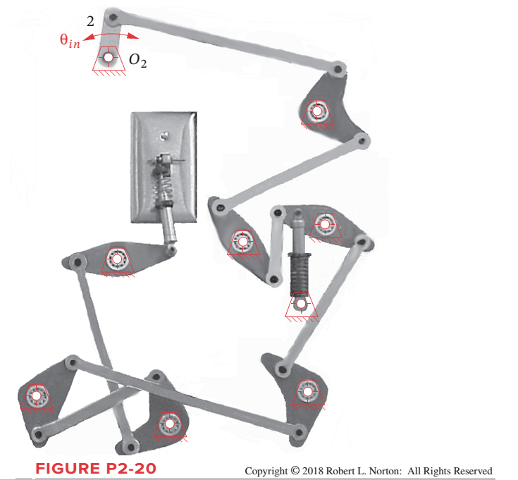
Chapter 2, Problem 2.44P
Figure P2-20 shows a “Rube Goldberg”
Expert Solution & Answer
Want to see the full answer?
Check out a sample textbook solution
Students have asked these similar questions
Figure below shows a four-bar linkage (non-scaled diagram) at an instant. The input
angle is equal to the output angle (02 - 04) and the transmission angle is 30°. The
input link is extended beyond joint B and an input force (Fin) is applied at the end of
it, while an output force is drawn from the midpoint of the output link. If an output
force of 30 N is desired from an input force of 10 N, how far the input link should be
extended, i.e., what is the distance from point B to the point where Fin is applied.
Fin
B
out
undefined
02
04
A.
Non-scaled diagram; AB = 10, CD=r4 = 30 (output), all in mm
The lengths of various links of a mechanism, as shown in Figure 2, are:
OA = 0.3 m; AB = 1 m; CD = 0.8 m; and AC = CB.
A
upuu
45°
Figure 2: Slider cranck mechanism
Draw the displacemt diagram to a scale.
1. Find a combination
of link lengths where motion of a point on output link is one
quarter of a circle.
2. Find the value of all 0, 0, 0, and y in open and close configuration
Read the value of link lengths and the input angle 8., then use the
formulae given below to calculate the value of unknowns 03, 0, and y
K₁ = = K₂= d
K2
K3
=
a²-b²+c²+d²
2ac
A = cos 0₂ - K₁ - K₂ cos 0₂ + K3
B = -2 sin 0₂
C = K₁ (K₂ + 1) cos 02 + K3
-B± √B²-4AC
2A
0412 = 2tan-1
d
K₁ = —
K5
=
c²d²a²-6²
2ab
D = cos 0₂ - K₁ - K4 cos 0₂ + K5
E = -2 sin 0₂
FK₁+ (K₁ - 1) cos 02 +K5
0312
2 tan-1
(-E±
-E± √E²4DF
2D
Y = 04-03
Chapter 2 Solutions
DESIGN OF MACHINERY
Ch. 2 - Find three (or other number as assigned) of the...Ch. 2 - How many DOF do you have in your wrist and hand...Ch. 2 - How many DOF do the following joints have? Your...Ch. 2 - How many DOF do the following have in their normal...Ch. 2 - Are the joints in Problem 2-3 force closed or form...Ch. 2 - Describe the motion of the following items as pure...Ch. 2 - Calculate the mobility of the linkages assigned...Ch. 2 - Identify the items in Figure P2-1 as mechanisms,...Ch. 2 - Use linkage transformation on the linkage of...Ch. 2 - Prob. 2.10P
Ch. 2 - Use number synthesis to find all the possible link...Ch. 2 - Prob. 2.12PCh. 2 - Use linkage transformation to create a 1-DOF...Ch. 2 - Use linkage transformation to create a 1-DOF...Ch. 2 - Calculate the Grashof condition of the fourbar...Ch. 2 - Prob. 2.16PCh. 2 - Describe the difference between a cam-follower...Ch. 2 - Examine an automobile hood hinge mechanism of the...Ch. 2 - Find an adjustable arm desk lamp of the type shown...Ch. 2 - The torque-speed curve for a 1/8 hp permanent...Ch. 2 - Find the mobility of the mechanisms in Figure...Ch. 2 - Find the Grashof condition and Barker...Ch. 2 - Find the rotatability of each loop of the...Ch. 2 - Find the mobility of the mechanisms in Figure...Ch. 2 - Find the mobility of the ice tongs in Figure P2-6:...Ch. 2 - Prob. 2.26PCh. 2 - Prob. 2.27PCh. 2 - Find the mobility of the corkscrew in Figure P2-9.Ch. 2 - Figure P2-10 shows Watts sun and planet drive that...Ch. 2 - Figure P2-11 shows a bicycle handbrake lever...Ch. 2 - Figure P2-12 shows a bicycle brake caliper...Ch. 2 - Find the mobility, the Grashof condition, and the...Ch. 2 - The approximate torque-speed curve and its...Ch. 2 - Prob. 2.34PCh. 2 - Prob. 2.35PCh. 2 - Sketch the equivalent linkage for the cam and...Ch. 2 - Describe the motion of the following rides,...Ch. 2 - For the mechanism in Figure P2-1 a, number the...Ch. 2 - Repeat Problem 2-38 for Figure P2-1b.Ch. 2 - Repeat Problem 2-38 for Figure P2-1c.Ch. 2 - Prob. 2.41PCh. 2 - Find the mobility, the Grashof condition, and the...Ch. 2 - Find the mobility, the Grashof condition, and the...Ch. 2 - Figure P2-20 shows a Rube Goldberg mechanism that...Ch. 2 - All the eightbar linkages in Figure 2-11 part 2...Ch. 2 - Prob. 2.46PCh. 2 - Prob. 2.47PCh. 2 - Find the mobility of the mechanism shown in Figure...Ch. 2 - Find the mobility of the mechanism shown in Figure...Ch. 2 - Find the mobility of the mechanism shown in Figure...Ch. 2 - Find the mobility of the mechanism shown in Figure...Ch. 2 - Prob. 2.52PCh. 2 - Prob. 2.53PCh. 2 - Repeat Problem 2-38 for Figure P2-1f.Ch. 2 - Repeat Problem 2-38 for Figure P2-1g.Ch. 2 - For the example linkage shown in Figure 2-4 find...Ch. 2 - For the linkage shown in Figure 2-5b find the...Ch. 2 - Prob. 2.58PCh. 2 - Figure P2-21b shows a mechanism. Find its mobility...Ch. 2 - Prob. 2.60PCh. 2 - Figure P2-21 d shows a log transporter. Draw a...Ch. 2 - Figure P2-21e shows a plow mechanism attached to a...Ch. 2 - Figure P2-22 shows a Hart inversor sixbar linkage....Ch. 2 - Figure P2-23 shows the top view of the partially...Ch. 2 - Figure P2-24a shows the seat and seat-back of a...Ch. 2 - Figure P2-24b shows the mechanism used to extend...Ch. 2 - Figure P2-24b shows the mechanism used to extend...Ch. 2 - Figure P2-25 shows a sixbar linkage. Is it a Watt...Ch. 2 - Use number synthesis o find all the possible link...Ch. 2 - Use number synthesis to find all the possible link...Ch. 2 - Prob. 2.71PCh. 2 - For the mechanism in Figure P2-26, number the...Ch. 2 - Figure P2-27 shows a schematic of an exercise...Ch. 2 - Calculate the mobility of the linkage in Figure...Ch. 2 - Calculate the Grashof condition of the fourbar...Ch. 2 - The drum brake mechanism in Figure P2-4g is a...
Knowledge Booster


Learn more about
Need a deep-dive on the concept behind this application? Look no further. Learn more about this topic, mechanical-engineering and related others by exploring similar questions and additional content below.Similar questions
- Get the degree of freedom of the following mechanism. Pin in Siot ofarrow_forwardConsider the Four-Degree-of-Freedom robot shown in figure Q1, and usethe following hints in your answer:Hint 1- Use frames {OO}, {O1} and {O4} as indicated in figure Q1.Hint 2- A joint can undergo a twist and a rotation at the same timearrow_forwardQ1: For a four-bar linkage. If a=5.5m, b=6m, c=8m and d=D10m. 1: Find the minimum of the transmission angle in degrees 2: Find the maximum of the transmission angle in degrees 3: Find 0, at the toggle positions in degrees bolaarrow_forward
- Q1/ Number the links on two of the mechanisms shown in Figures (1 & 2 & 3 & 4 & 5) then, calculate the number of degrees of freedom. FIG. 1 FIG. 1 FIG. 2 FIG. 1 FIG. 3 Bo 16arrow_forwardThe reversing motor,which is controlled by two power relays,can be rotated in both directions as shown in the figure beiow.When the motor is mechanically combined with a lead screw,the rotary motion is converted to a linear one,such as the one moving lef tor right on the worktable in the layout.The desired direction of rotation is selected via the two STAFIT buttons,respectively.The limit switches LS1 and LS2,located at the two extreme motion limits,ensure 1-rqtf we forget to stop the movement of the worktable,then it will stop automatically, and the mechanism of the layout will not be destroyed.Draw the circuit of automation.arrow_forwardFind the degrees of freedom of the mechanism in the figure.arrow_forward
- Write and draw the following grashof's criterion and kind of grashof's four-bar mechanism such as; 1. Crank-rocker mechanism; 2. Drag link mechanism; 3. Double rocker mechanism; 4. Crossover-position or charge-point mechanism; 5 Triple rocker mechanism (non-grashof). Use technical Pen for the following: 0.2(light -for linkages and hand writing), 0.4(medium - for joints), 0.6(heavy - for fixed link or frames) use 2-4-4 template, all caps, italicized.arrow_forwardThe number of degrees of freedom of the linkage shown in the figure.arrow_forwardDOF for the following mechanism is .3 2arrow_forward
- Draw the kinematic diagram of the following mechanism by labelling the links and the joints and calculate its mobility / DOF.arrow_forwardThe kinematic scheme of the mechanism is given. Point C is the center of curvature of the link 3 at the point of the contact. Link 2 is with circular shape with center point B. Find the degrees of freedom.arrow_forwardCalculate the Degree of Freedom (DOF) of the following mechanism.arrow_forward
arrow_back_ios
SEE MORE QUESTIONS
arrow_forward_ios
Recommended textbooks for you
 Elements Of ElectromagneticsMechanical EngineeringISBN:9780190698614Author:Sadiku, Matthew N. O.Publisher:Oxford University Press
 Mechanics of Materials (10th Edition)Mechanical EngineeringISBN:9780134319650Author:Russell C. HibbelerPublisher:PEARSON
 Thermodynamics: An Engineering ApproachMechanical EngineeringISBN:9781259822674Author:Yunus A. Cengel Dr., Michael A. BolesPublisher:McGraw-Hill Education
 Control Systems EngineeringMechanical EngineeringISBN:9781118170519Author:Norman S. NisePublisher:WILEY
 Mechanics of Materials (MindTap Course List)Mechanical EngineeringISBN:9781337093347Author:Barry J. Goodno, James M. GerePublisher:Cengage Learning
 Engineering Mechanics: StaticsMechanical EngineeringISBN:9781118807330Author:James L. Meriam, L. G. Kraige, J. N. BoltonPublisher:WILEY
Elements Of Electromagnetics
Mechanical Engineering
ISBN:9780190698614
Author:Sadiku, Matthew N. O.
Publisher:Oxford University Press
Mechanics of Materials (10th Edition)
Mechanical Engineering
ISBN:9780134319650
Author:Russell C. Hibbeler
Publisher:PEARSON
Thermodynamics: An Engineering Approach
Mechanical Engineering
ISBN:9781259822674
Author:Yunus A. Cengel Dr., Michael A. Boles
Publisher:McGraw-Hill Education
Control Systems Engineering
Mechanical Engineering
ISBN:9781118170519
Author:Norman S. Nise
Publisher:WILEY
Mechanics of Materials (MindTap Course List)
Mechanical Engineering
ISBN:9781337093347
Author:Barry J. Goodno, James M. Gere
Publisher:Cengage Learning
Engineering Mechanics: Statics
Mechanical Engineering
ISBN:9781118807330
Author:James L. Meriam, L. G. Kraige, J. N. Bolton
Publisher:WILEY
Force | Free Body Diagrams | Physics | Don't Memorise; Author: Don't Memorise;https://www.youtube.com/watch?v=4Bwwq1munB0;License: Standard YouTube License, CC-BY