
Videos
Consider the circuit shown in Figure P2.47. Assume each diode cut−in voltage is
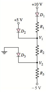
Figure P2.47
(a)
The values of
Answer to Problem 2.47P
The required values are,
Explanation of Solution
Given:
Diode’s cut-in voltage =
Calculation:
Assume all diode are conducting.
Draw the circuit diagram with node voltages and cut-in voltages.
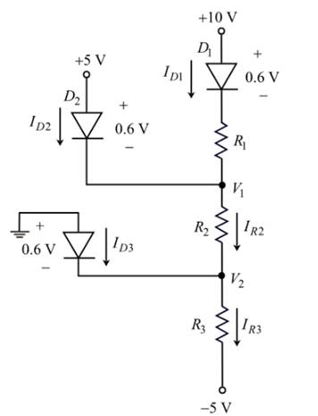
Figure 1
From Figure 1, the voltage at node
The voltage at node
Write the expression for current following through diode
Substitute
Therefore, the value of the resistor,
Apply Kirchhoff’s current law at node
Substitute
Calculate the value of resistor
Substitute
Therefore, the value of the resistor
Apply Kirchhoff’s current law at node
Substitute
Calculate the value of resistor
Substitute
Therefore, the value of the resistor,
Conclusion:
Therefore, the required values are
(b)
To find: The values of
Answer to Problem 2.47P
The required values are,
Explanation of Solution
Given:
Diode’s cut-in volt- age is
Calculation:
Assume at diodes are conducting.
From Figure 1, the voltage at node
The voltage at node
Calculate the current,
Substitute
Therefore, the current following through diode
Calculate the current following through resistor
Substitute
Apply Kirchhoff’s current law at node
Substitute
Therefore, the current following diode
Calculate the current following through resistor,
Substitute
Apply Kirchhoff’s current law at node
Substitute
Therefore, the current following diode
Conclusion:
Therefore, the required values are
(c)
To find: The values of
Answer to Problem 2.47P
The require values are
Explanation of Solution
Given:
Diode’s cut-in volt- age is

Calculation:
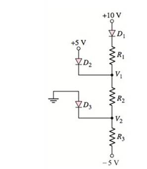
Assume diode
Draw the current diagram with node voltage and cut-in voltages.
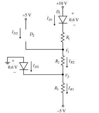
Figure 2
In Figure 2, the Diode
That is,
Therefore, the current following through diode
From Figure 2, the voltage at node
Apply Kirchhoff’s current law at node
Substitute
Calculate the current
Substitute
Therefore, the current following diode
From Figure 2,
Calculate the current following through resistor,
Substitute
Apply Kirchhoff’s current law at node
Substitute
Therefore, the current following diode
(d)
To find: The values of
Answer to Problem 2.47P
The required values are
Explanation of Solution
Given:
Diode’s cut-in volt- age is
Calculation:
Assume diode
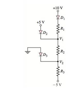
Draw the circuit diagram with node voltages and cut-in voltages.
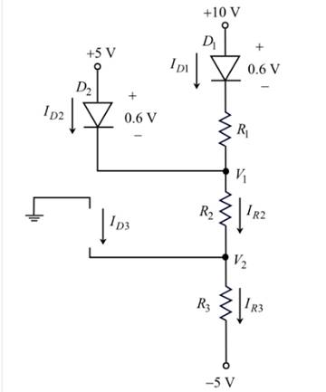
Figure 3
In Figure 3, the Diode
That is,
Therefore, the current following through diode
From Figure 1, the voltage at node
Therefore, the node voltage,
Apply Kirchhoff’s current law at node
Substitute
Calculate the current
Substitute
Therefore, the current following diode
Calculate the current following through resistor,
Substitute
Apply Kirchhoff’s current law at node
Substitute
Want to see more full solutions like this?
Chapter 2 Solutions
Microelectronics: Circuit Analysis and Design


- 4kN 2V Determine the state of diode for the circuit shown. find ID and VD. Assume simplified model for the diode. (Diode is Silicon). 4k2 2V 1k2. 0.7V O -0.375 mA, 0.4 V, off O -0.67 mA, -0.24 V, on O -1.5 mA, 0.7 v, off O 2.04 mA, -8 V, onarrow_forwardCalculate the diode current, lo, for the circuit shown. The source has Va 1.5 V and R = 0.8 92 and each of the diodes has Is = 10" A. // 21-15001 = 1.5 Vth R+h0.8 22 ↓ID vearrow_forwardFor the circuit shown in the Figure, if the diodes are silicon diodes with VD(on)=0.7 V, and VIn=50 sin wt V, V1 =7 V and V2 =13 V, then the value of VOUT (p-p) is: R1 D, D2 VIN VOUT vi E v2= Ca. 19.4 V Ob. 17.4 V Cc. 15.4 V Cd. 21.4 Varrow_forward
- Given the following circuit with VDD = 9.5 V, R = 3.2 k2, then the current Iis: Use the CVD model for the diode, with VD = 0.65 V. VDD I a. 0 A O b. 0.002766 A c. 0.002969 A d. 2.968750 A e. 2.765625 A R N V₂arrow_forwardIn each of the circuits shown below, find voltage V, and current I. Assume the 0.7 drop diode model. +5V +2.3V -4.7V lo 2.5 k2 4 k2 $ 3kn +1.3 V D1 ov. D1 V D2 A 2 knž 2kO 2 k2 -0.7V D2 2v 6 +8V a) b) c)arrow_forward2. Figure A.1 shows I-V characteristics of two diodes, namely A and B. Diode A has higher dynamic resistance than diode B. UTM &UT ID 4 5UTM 3TM UTM UTM &UTM 5 UTM & UTM UTM 3 UTM 03 TM 6 UT 0.68 (a) UTM VD Figure A.1 State one possible reason why the diodes have different knee voltage values. UTM OM & UTM 3 UTM & TM (b) Based on Figure A.1, identify the knee voltage of UTM" TM 5 UTde BE UTMarrow_forward
- In the circuit given in the figure, find the current passing through the diode in mA since R1 = 4.95Kohm, R2 = 2.50Kohm, R3 = 1.69Kohm, R4 = 5.44Kohm, VCC = 13.00V and the diode is silicon?arrow_forwardFor the circuit shown in the Figure, if the diodes are silicon diodes with Vp(on)=0.7 V, and VIN=50 sin wt V, V1 =6 V and V2 = 16 V, then the value of VouTP-p) is: R, D VaN Vout v1事 2章 Oa. 25.4 V Ob. 27.4 V Oc. 29.4 V Od. 23.4 Varrow_forwardFor the circuit below, assume the diodes operate with a constant voltage drop of .7V, find Vx, Vy, VD4 and ID2. 15V 15V Allt V1 V2 R1 1k IDC 1mA Vx R2 2k ww D1N4002 Vy D1N4002 7D1 D1N4002 D2 D3 R3 1k D4 D1N4002arrow_forward
- Plot the input/output characteristics of the circuits shown below using both ideal diode mode and constant-voltage model with VD, on= 0.8 V, where R₁= 2k, and R₂= 5 KQ, and VB 1.8 V in (c). (a) (c) D₁ R₁ Vinº * W R1 + WWF K D2R₂ D₁ ww Vout o Vout R₂ (b) Vino D₁ . R₁ KWI D₂ R₂ Voutarrow_forward(a) State one possible reason why the diodes have different knee voltage values. 2. Figure A.1 shows I-V characteristics of two diodes, namely A and B. Diode A has UTM higher dynamic resistance than diode B. 5 UTM U UTM Ip UTM TM 3 UTM UTM O UTM UTM UTM UTM & UTM 03 TM UTM 0.68 VD Figure A.1 State one possible reason why the diodes have different knee voltage values. 5 UTM & UTM M 3 UTM (b) Based on Figure A.1, identify the knee voltage of UTM (c) Draw with complete labelling an equivalent circuit that represents the circuit in UFigure A.2. Consider practical diode model. TM 5 UTM 5 UPde BE UTM & UTM & UTM 1 ΚΩ Diode B 5 UTM O UTM UTM & UTM & UTM 1.5 V 5 UTM UT 5 UTM 3 V 5 UTM O UTM Figure A.2 M G UTM 5 UTM 5 UTM & UTM 5 UTM UTMarrow_forwardConsider the diode circuit below, with both diodes having 0.7 V across them when they conduct. V(1) = 10sinwt V (AC)V(2) = 4 V (DC)R(1) = R (2) = 1.3 k(ohm) Over a full cycle of the AC input: 1. Calculate the maximum current through diode 1 (D1). Explain and show all steps. 2. Find the voltage across each resistor. Explain and show all steps. 3. Sketch the current waveform across diode 2 (D2). Label all important points. Explain and show all steps.arrow_forward
