
Concept explainers
Videos
a.
Draw the correct symbol for the description “Lighting panel”.
a.
Explanation of Solution
The symbol for the lighting panel is drawn and it is shown in Figure 1 as follows:
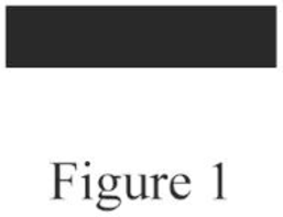
Conclusion:
Thus, the symbol for the given description is drawn.
b.
Draw the correct symbol for the description “Clock outlet”.
b.
Explanation of Solution
The symbol for the clock outlet is drawn and it is shown in Figure 2 as follows:
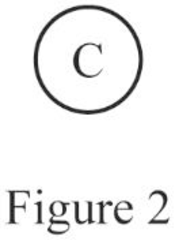
Conclusion:
Thus, the symbol for the given description is drawn.
c.
Draw the correct symbol for the description “Duplex outlet”.
c.
Explanation of Solution
The symbol for the duplex outlet is drawn and it is shown in Figure 3 as follows:
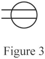
Conclusion:
Thus, the symbol for the given description is drawn.
d.
Draw the correct symbol for the description “Outside telephone”.
d.
Explanation of Solution
The symbol for the outside telephone is drawn and it is shown in Figure 4 as follows:

Conclusion:
Thus, the symbol for the given description is drawn.
e.
Draw the correct symbol for the description “Single-pole switch”.
e.
Explanation of Solution
The symbol for the single-pole switch is drawn and it is shown in Figure 5 as follows:
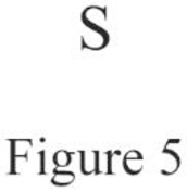
Conclusion:
Thus, the symbol for the given description is drawn.
f.
Draw the correct symbol for the description “Motor”.
f.
Explanation of Solution
The symbol for the motor is drawn and it is shown in Figure 6 as follows:

Conclusion:
Thus, the symbol for the given description is drawn.
g.
Draw the correct symbol for the description “Duplex outlet, split-wired”.
g.
Explanation of Solution
The symbol for the duplex outlet, split-wired is drawn and it is shown in Figure 7 as follows:
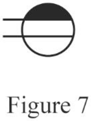
Conclusion:
Thus, the symbol for the given description is drawn.
h.
Draw the correct symbol for the description “Lampholder with pull switch”.
h.
Explanation of Solution
The symbol for the lampholder with pull switch is drawn and it is shown in Figure 8 as follows:

Conclusion:
Thus, the symbol for the given description is drawn.
i.
Draw the correct symbol for the description “Weatherproof outlet”.
i.
Explanation of Solution
The symbol for the weatherproof outlet is drawn and it is shown in Figure 9 as follows:
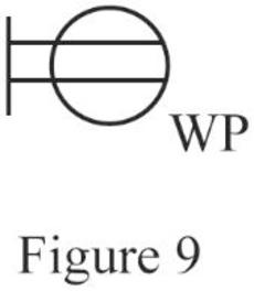
Conclusion:
Thus, the symbol for the given description is drawn.
j.
Draw the correct symbol for the description “Special-purpose outlet”.
j.
Explanation of Solution
The symbol for the special-purpose outlet is drawn and it is shown in Figure 10 as follows:
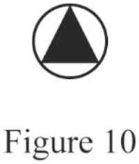
Conclusion:
Thus, the symbol for the given description is drawn.
k.
Draw the correct symbol for the description “fan outlet”.
k.
Explanation of Solution
The symbol for the fan outlet is drawn and it is shown in Figure 11 as follows:
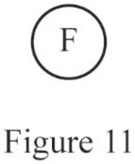
Conclusion:
Thus, the symbol for the given description is drawn.
l.
Draw the correct symbol for the description “Range outlet”.
l.
Explanation of Solution
The symbol for the range outlet is drawn and it is shown in Figure 12 as follows:
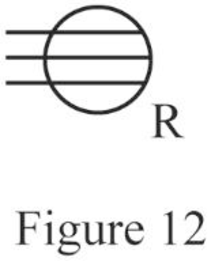
Conclusion:
Thus, the symbol for the given description is drawn.
m.
Draw the correct symbol for the description “Power panel”.
m.
Explanation of Solution
The symbol for the power panel is drawn and it is shown in Figure 13 as follows:
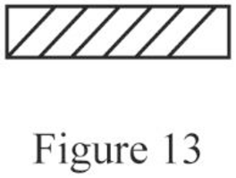
Conclusion:
Thus, the symbol for the given description is drawn.
n.
Draw the correct symbol for the description “3-way switch”.
n.
Explanation of Solution
The symbol for the 3-way switch is drawn and it is shown in Figure 14 as follows:
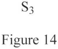
Conclusion:
Thus, the symbol for the given description is drawn.
o.
Draw the correct symbol for the description “Push button”.
o.
Explanation of Solution
The symbol for the push button is drawn and it is shown in Figure 15 as follows:
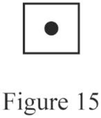
Conclusion:
Thus, the symbol for the given description is drawn.
p.
Draw the correct symbol for the description “Thermostat”.
p.
Explanation of Solution
The symbol for the thermostat is drawn and it is shown in Figure 16 as follows:
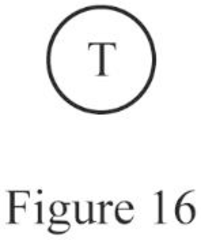
Conclusion:
Thus, the symbol for the given description is drawn.
q.
Draw the correct symbol for the description “Electric door opener”.
q.
Explanation of Solution
The symbol for the electric door opener is drawn and it is shown in Figure 17 as follows:
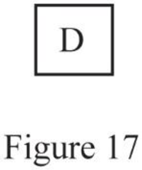
Conclusion:
Thus, the symbol for the given description is drawn.
r.
Draw the correct symbol for the description “Multioutlet assembly”.
r.
Explanation of Solution
The symbol for the multioutlet assembly is drawn and it is shown in Figure 18 as follows:
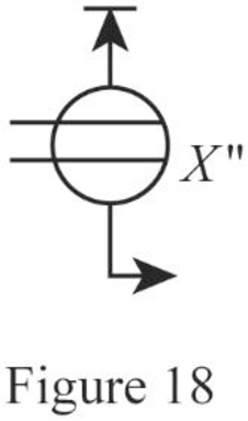
Where,
Conclusion:
Thus, the symbol for the given description is drawn.
Want to see more full solutions like this?
Chapter 2 Solutions
EBK ELECTRICAL WIRING RESIDENTIAL


- Two of the circuits will be a 3-wire, multi-wire branch circuit (Edison 3-wire). The location of the devices is to be determined by the student. The student shall be responsible for selecting the correct circuits, do not ask the instructor which circuit number should be used. Circuit A. One lampholder and one duplex receptacle controlled by a Single Pole Switch. Circuit B. Single Pole Switch controlling the top half of a duplex receptacle that when energized, is indicated by a Pilot-light at the Single Pole Switch location; plus an Isolated Ground Duplex Receptacle that is always hot. Circuit C. The bottom half of the switched receptacle on Circuit ‘B’ is to be always hot; plus another Duplex Receptacle that is controlled from two locations using a Coast 3-Way wiring-system.arrow_forwardThe National Electrical Code® requires that all switching be done in the __________ circuit conductor. Select one: A. GROUNDED B. SWITCH LOOP C. GROUNDING D. UNGROUNDEDarrow_forward4.A. If a bonding jumper is installed from a grounded metal box to a grounding-type receptacle, the length ofthe bonding jumper will be betweenA. 2 and 4 feet.B. 2 and 4 inches.C. 6 and 10 feet.D. 6 and 10 inches.4.B. Why isn't solder permitted to be relied on for grounding electrode connections?A. The solder increases the chances of a ground-fault event occurring.B. The heat from the solder weakens the connection and exposes it to physical damage.C. The use of solder doesn't meet the requirements for corrosive influences.D. The connection's integrity can be negatively affected by heat during a ground-fault event.4>c. Which of the following statements about bonding is true?A. The strike terminals of a lightning protection system must be bonded to the building or structure grounding electrode system.B. Bonding requirements on the supply side of the service disconnect are less restrictive.C. Wire-type supply-side bonding jumpers are usually short in length and installed from the…arrow_forward
- Raceway fill calculations are a prerequisite in ____ needed for particular circuits. Select one: A. MATERIAL REQUIREMENTS B. SCHEMATIC REQUIREMENTS C. DETERMINING THE SIZE OF RACEWAY D. CIRCUIT LOADSarrow_forwardFollow the procedures in troubleshooting the defects and faults of an electric fan by filling in the missing steps.Doesn't rotate 1.___________ 2.____________ Check for Open AC cord or wiring3. ___________4.___________ Defective switch/electronic system control 5. _____________Defective module (system control).arrow_forwardIf two 115-volt loads were connectedin parallel with 240 volts, they would__________.a. burn dimlyb. immediately burn outc. burn correctlyd. none of the abovearrow_forward
- A means shall be provided in each metal box over 100 cubic inches for the connection of an equipment grounding conductor. The means shall be permitted to be ______. a tapped hole the cover screw III. a screw used to mount the box (a.) I only (c.) I & II only (b.) II only (d.) I, II or IIIarrow_forwardReceptacle and cord terminals should be marked as follows;A. “X” and “O” ungrounded, “W” grounded and “G” equipment groundingB. “Y” and “X” ungrounded, “N” grounded and “GR” equipment groundingC. “X” and “O” ungrounded, “W” grounded and “E” equipment groundingD. “X” and “Y” ungrounded, “W” grounded and “G” equipment groundingarrow_forwardThe circuit breaker cubicles illustrated in your reading material each contain____circuit breakers. A. Two B. Three C. Four D. Sixarrow_forward
- 1.1 PV modules can be wired together in an array using ______ connections to increase voltage. a. Terminating b. Series c. Parallel d. AC 1.2 A PV module, also called a solar panel, is comprised of individual photovoltaic _______ wired and mounted together as an integrated unit. a. Capsules b. Compartments c. Chips d. Cells 1.3 A __________ system uses a storage system that stores the generated electricity so it can provide during times when the system’s panels are not receiving solar energy. a. Direct coupled b. Self regulating c. Charge controlled d. Indirectly connected 1. 4 __________ energy may have the potential to supply all of the world's energy needs, but at this time, it provides a very small percentage. a. Coal b. Natural Gas c. Diesel d. Solararrow_forward5.a. Typically, the bonding conductor installed between the panelboard equipment grounding terminal barsmust be continuous. It's only allowed to be broken where it connects to theA. signal reference grid.B. terminal bar in the panelboard.C. branch circuit.D. service entrance enclosure.5.b. An electrical system that's not grounded and is between 120 and 1000 volts must include the use ofA. arc suppression.B. ground isolators.C. ground detectors.D. equipotential barriers.arrow_forward5. An automatic switch or cutout is allowed in the equipment grounding conductor circuit when A. there's a redundant equipment grounding conductor in the circuit. B. the power sources are disconnected when operated. C. it's bonded around the disconnecting device. D. it also opens the neutral.arrow_forward
 Introductory Circuit Analysis (13th Edition)Electrical EngineeringISBN:9780133923605Author:Robert L. BoylestadPublisher:PEARSON
 Delmar's Standard Textbook Of ElectricityElectrical EngineeringISBN:9781337900348Author:Stephen L. HermanPublisher:Cengage Learning
 Programmable Logic ControllersElectrical EngineeringISBN:9780073373843Author:Frank D. PetruzellaPublisher:McGraw-Hill Education
 Fundamentals of Electric CircuitsElectrical EngineeringISBN:9780078028229Author:Charles K Alexander, Matthew SadikuPublisher:McGraw-Hill Education
 Electric Circuits. (11th Edition)Electrical EngineeringISBN:9780134746968Author:James W. Nilsson, Susan RiedelPublisher:PEARSON
 Engineering ElectromagneticsElectrical EngineeringISBN:9780078028151Author:Hayt, William H. (william Hart), Jr, BUCK, John A.Publisher:Mcgraw-hill Education,