Concept explainers
Videos
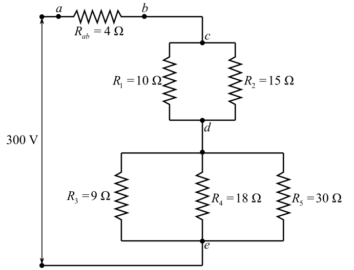
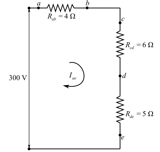
For the circuit shown in Fig. 28-14, find (a) its equivalent resistance; (b) the current drawn from the power source; (c) the potential differences across ab, cd, and de; (d) the current in each resistor.
![Chapter 28, Problem 31SP, 28.31 [II] For the circuit shown in Fig. 28-14, find (a) its equivalent resistance; (b) the current](https://content.bartleby.com/tbms-images/9781259587399/Chapter-28/images/87399-28-31sp-question-digital_image79.png)
Fig. 28-14
(a)
The net resistance across the circuit provided in the figure 28-14 in the textbook.
Answer to Problem 31SP
Solution:
Explanation of Solution
Given data:
The resistances
The resistances
The resistance across circuit
The voltage across the terminal
Formula used:
The expression for the equivalent resistance in series is written as
Here,
The expression for the equivalent resistance in parallel is written as
Here,
Explanation:
Refer to the fig. 28-14from the textbook.
Draw the circuit diagram:
Since, the resistance
Write the expression for the resistances across
Here,
Substitute
Solve for
Modify the above drawn circuit diagram by using
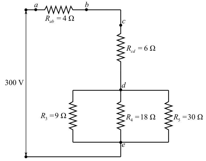
Understand that the resistors
Here,
Substitute
Here,
Redraw the modified circuit diagram by using the calculated equivalent resistances across the nodes:
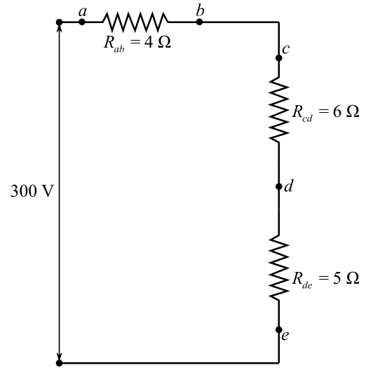
Since, all the resisters in the above diagram arein series combination.
Write the expression for the total resistance of the equivalent resistances across
Here,
Substitute
Conclusion:
The net resistance across the point
(b)
The current drawn from the source if the voltage across the circuit is
Answer to Problem 31SP
Solution:
Explanation of Solution
Given data:
Voltage across the circuit is
Formula used:
The expression for theOhm`s law if net current
Explanation:
Redraw the equivalent circuit diagram:
In the above diagram,
Rewrite the expression of the Ohm`s law for the net current across circuit
Here,
Rearrange for
Here,
Substitute
Conclusion:
Therefore, the current drawn from the source is
(c)
The voltage difference across circuits
Answer to Problem 31SP
Solution:
Explanation of Solution
Given data:
The current across
The resistances of the resistor are provided in the figure as
Formula used:
The expression for the net Voltage
Explanation:
The current in the series combination of circuits
Write the expression for the voltage across circuit
Here,
Substitute
Write the expression for the voltage across circuit
Here,
Substitute
Write the expression for the voltage across circuit
Here,
Substitute
Conclusion:
The voltages across circuits
(d)
The current across each resistor if the voltage and current across each circuit are known.
Answer to Problem 31SP
Solution:
Explanation of Solution
Given data:
The voltage across the circuit
The voltage across the circuit
The voltage across the circuit
The current across the circuit
Formula used:
The expression for the net voltage
Explanation:
In this, wewill use the fact that voltage across each resistor in a parallel combination of resistors remains same.
According to the Ohm’s law, the current across the
Rearrange for
Here
Substitute
The voltage across the parallel combination of resistance
Write the expression for the current across
Rearrange for
Here,
Substitute
Write the expression for the current across
Rearrange for
Here,
Substitute
The voltage across the parallel combination of resistors
Write the expression for the current across
Rearrange for
Here,
Substitute
Write the expression for the current across
Rearrange for
Here,
Substitute
Write the expression for the current across
Rearrange for
Here,
Substitute
Conclusion:
The current across the
Want to see more full solutions like this?
Chapter 28 Solutions
Schaum's Outline of College Physics, Twelfth Edition (Schaum's Outlines)


- The power dissipated in a resistor is given by P = V2/R, which means power decreases if resistance increases. Yet this power is also given by P = I2R, which means power increases if resistance increases. Explain why there is no contradiction here.arrow_forwardRefer to Figure 10.17 and the discussion of lights dimming when a heavy appliance comes on. (a) Given the voltage source is 120 V, the wire resistance is 0.800 and the bulb is nominally 75.0 W, what power will the bulb dissipate if a total of 15.0 A passes through the wires when the motor comes on? Assume negligible change in bulb resistance, (b) What power is consumed by the motor?arrow_forwardShow that if two resistors R1and R2are combined and one is much greater than the other (R 1 >>R 2 ): (a) Their series resistance is very nearly equal to the greater resistance R 1. (b) Their parallel resistance is very nearly equal to smaller resistance R2.arrow_forward
- Check Your Understanding If you place a wire directly across the two terminal of a battery, effectively shorting out the terminals, the battery will begin to get hot. Wiry do you suppose this happens?arrow_forward(a) Find the equivalent resistance between points a and b for the combination shown in Fig. 28-6 A current of 5.0 A flows into the circuit in Fig. 28-6 at point a and out at point b. (a) What is the potential difference from a to b? (b) How much current flows through the 12.0-ohms resistor?arrow_forwardFor the circuit shown in Fig. 28-17, find (a) the equivalent resistance; (b) the currents through the 5.0-2, 7.0-2, and 3.0-2 resistors; (c) the total power delivered by the battery to the circuit. 6.0 2 3.0 2 7.0 2 2.02 8.0 Q 5.0 2 E = 120 V r= 1.0 2arrow_forward
- Choose the words that make each statement correct. (i) Whentwo or more resistors are connected in series, the equivalentresistance is always [(a) greater than; (b) less than] anyindividual resistance. (ii) When two or more resistors areconnected in parallel, the equivalent resistance is always [(c)greater than; (d) less than] any individual resistance.arrow_forwardAs shown in Fig. 28-2(a), a battery (internal resistance I 2) is connected in series with two resistors. Compute (a) the current in the circuit, (b) the p.d. across each resistor, and (c) the terminal p.d. of the battery. 6. E- 18 V r-12 -W- -W 122 (a) Fig. 28-2arrow_forward27-1. In Figure, the ideal batteries have emfs E,= 10.0 V and Ez = 0.500 E, , and the resistances are each 4.00 2. What is the current in (a) resistance 2 and (b) resistance 3? ww R +18, 8,arrow_forward
- (69%) Problem 10: In the figure, these three resistors are counected to a voltage source so that Ry = 5.5 a and R3 = 8.5 2 are in parallel with one anotber and that combination is in series with R = 0.75 0. R z = ? 12.0 V R R3 2 * 50% Part (a) Calculate the power being dissipated by the third resistor R3. in watts. Grade Summary P;- Deductions Potentiul 100% Late Work % 75%% sin() cos() lani) 7 OME Late Putential cotan() asin) acos() E 4 5 6 Submissions sinh) 23 Attempts remaining: 996 (0% per attermpt) detailed view atan() acotan() cosh() tanh() cotanh) END O Degrees C Radians 0% VO DACKSACE CLBAR 1 2 0% 0% Hint I give up Suhmit Feedbackarrow_forward10) The voltage I in a simple clectrical circnit is slowly decreasing as the battery wears out. The resistance R is slowly incriasting as itneresistor heats up Use Olm's Law. F= IR to lind lhow the curent /is changing at the moment when R= 400 2 /=0,08 A. dt di 0.01 Vis nd 0.031/sarrow_forward(6) Suppose two electrical resistors with resistance R₁> 0 and R₂ > 0 are wired in parallel in a circuit: R₁ ww R₂ 1 1 1 + Then the combined resistance R, measured in ohms (2), is given by R R₁ R₂ ƏR ƏR (a) Find and after solving for R (e.g., R= ...). ƏR₁ ƏR₂ (b) Describe how an increase in R₁ with R₂ held constant will change R. (Will R increase or decrease?) (c) Describe how a decrease in R₂ with R₁ held constant will hange R. (Will R increase or decrease?)arrow_forward
 College PhysicsPhysicsISBN:9781938168000Author:Paul Peter Urone, Roger HinrichsPublisher:OpenStax College
 Principles of Physics: A Calculus-Based TextPhysicsISBN:9781133104261Author:Raymond A. Serway, John W. JewettPublisher:Cengage Learning
 Glencoe Physics: Principles and Problems, Student...PhysicsISBN:9780078807213Author:Paul W. ZitzewitzPublisher:Glencoe/McGraw-Hill