
Concept explainers
Calculate the power dissipated in each resistor in the circuit of Figure 3.104.
Answer to Problem 60P
The power dissipated in
Explanation of Solution
Given data:
Refer to Figure 3.104 in the textbook for the nodal analysis. In the given circuit,
Calculation:
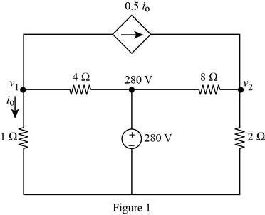
Modify the given figure with the representation of node voltage as shown in Figure 1.
Apply Kirchhoff’s current law at node
With reference to Figure 1, write the expression for
Substitute equation (2) in (1).
Simplify the equation as follows.
Apply Kirchhoff’s current law at node
Substitute equation (2) in (3).
Substitute
Simplify the equation as follows.
Write the expression for power dissipated through
Substitute
Write the expression for power dissipated through
Substitute
Write the expression for power dissipated through
Substitute
Write the expression for power dissipated through
Substitute
Conclusion:
Therefore, the power dissipated in
Want to see more full solutions like this?
Chapter 3 Solutions
Fundamentals of Electric Circuits


- Q3: Find the equivalent circuit between the terminals a and b, then find the value of Rithat can be place between the terminals to deliver the maximum power from the source Hint: use RL values smaller, equal, greater than RTh, then decide which one you have to pick! 30 Ω a 360 V 150 Ωξ RL barrow_forward3.40 For the bridge network in Fig. 3.86, find i, using Homesh analysis. ML 56 V Figure 3.86 For Prob. 3.40. + 2 ΚΩ ww 6 ΚΩ Μ Μ Μ 4 ΚΩ 2 ΚΩ Μ 6 ΚΩ 4 ΚΩarrow_forwardUse superposition to calculate the voltage Vo, if Is = 3, R = 2, and Vs = 12.arrow_forward
- 3.42 In the circuit of Fig. 3.85, solve for i, iz, and iz. 10 V ww IA 20 4A 120 8V Figure 3.85 For Prob. 3.42.arrow_forward*3.55 In the circuit of Fig. 3.100, solve for I₁, I2, and 13. # ML 4 A Figure 3.100 For Prob. 3.55. ww 652 1292 10 V 1, 8 V DIA 1A 492 3202arrow_forward3.13 Calculate v₁ and U₂ in the circuit of Fig. 3.62 using nodal analysis. 852 VI Figure 3.62 For Prob. 3.13. 252 www 10 V 452 1/2 www 15 Aarrow_forward
- use Superposition principle: a) determine the contribution from the voltage source alone. b) determine the contribution from the current source alone. c)determine the total current with both sources active.arrow_forward3.36 Use mesh analysis to obtain i, iz, and iz in the circuit in Fig. 3.84. 10 V ww 12 V Figure 3.84 For Prob. 3.36.arrow_forward1. For the circuit shown below, find: i) the total current ii) the current in the 8 Q resistor iii) the voltage drop across the 3N resistorarrow_forward
- 3.57 In the circuit of Fig. 3.102, find the values of R, V1, and V2 given that i, 15 mA. + 3 k2 90 V 4 k2 V2 Figure 3.102 For Prob. 3.57.arrow_forwardblems / 3.9 Determine 7, in the circuit in Fig. 3.58 using nodal analysis. 24 V Figure 3.58 For Prob. 3.9. 250 92 www www 601 + 50 52 www 115 150 Ωarrow_forwardDetermine U, and v, in the circuit of Fig. 3.71. 12 V +1 ΖΩ 1 www. 41 8 Ω www 34 4 Ω + 12 ΤΩ 500arrow_forward
 Introductory Circuit Analysis (13th Edition)Electrical EngineeringISBN:9780133923605Author:Robert L. BoylestadPublisher:PEARSON
 Delmar's Standard Textbook Of ElectricityElectrical EngineeringISBN:9781337900348Author:Stephen L. HermanPublisher:Cengage Learning
 Programmable Logic ControllersElectrical EngineeringISBN:9780073373843Author:Frank D. PetruzellaPublisher:McGraw-Hill Education
 Fundamentals of Electric CircuitsElectrical EngineeringISBN:9780078028229Author:Charles K Alexander, Matthew SadikuPublisher:McGraw-Hill Education
 Electric Circuits. (11th Edition)Electrical EngineeringISBN:9780134746968Author:James W. Nilsson, Susan RiedelPublisher:PEARSON
 Engineering ElectromagneticsElectrical EngineeringISBN:9780078028151Author:Hayt, William H. (william Hart), Jr, BUCK, John A.Publisher:Mcgraw-hill Education,