
Videos
Solve Prob. 3.55, assuming that the shaft AB is replaced by a hollow shaft of the same outer diameter and 25-mm inner diameter.
3.55 Two solid steel shafts (G = 77.2 GPa) are connected to a coupling disk B and to fixed supports at A and C. For the loading shown, determine (a) the reaction at each support, (b) the maximum shearing stress in shaft (c) the maximum shearing stress in shaft BC.
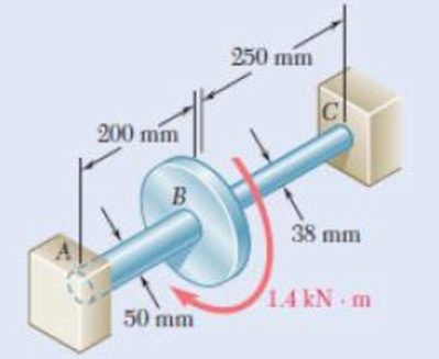
Fig. p3.55
(a)
The reaction at the supports.
Answer to Problem 56P
The reaction at the supports are
Explanation of Solution
Given information:
The modulus of rigidity of solid shafts is
Inner diameter of the shaft AB is 25 mm.
Calculation:
The outer radius of the shaft AB is
The inner radius of the shaft AB is
The polar moment of inertia of shaft AB of outer radius
The torque carried by the shaft AB
Here,
Substitute
The radius of the shaft BC is
The polar moment of inertia of shaft BC of radius
The torque carried by the shaft BC
Here,
Substitute
The value of total torque in the shaft is
The total torque
Substitute
Substitute
Therefore, the reaction at the supports are
(b)
The maximum shearing stress in the shaft AB.
Answer to Problem 56P
The maximum shearing stress in the shaft AB is
Explanation of Solution
Given information:
The modulus of rigidity of solid shafts is
Calculation:
Refer (a).
The value of torque in the shaft AB is
The polar moment of inertia of shaft AB is
The maximum shearing stress in the shaft AB
Substitute
Therefore, the maximum shearing stress in the shaft AB is
(c)
The maximum shearing stress in the shaft BC.
Answer to Problem 56P
The maximum shearing stress in the shaft BC is
Explanation of Solution
Given information:
The modulus of rigidity of solid shafts is
Calculation:
Refer (a).
The value of torque in the shaft BC is
The polar moment of inertia of shaft BC of radius
The maximum shearing stress in the shaft BC
Substitute
Therefore, the maximum shearing stress in the shaft BC is
Want to see more full solutions like this?
Chapter 3 Solutions
Mechanics of Materials, 7th Edition


- Two solid steel shafts (G = 77.2 GPa) are connected to a coupling disk B and to fixed supports at A and C. For the loading shown, determine (a) the reaction at each support, (b) the maximum shearing stress in shaft AB, (c) the maximum shearing stress in shaft BC. A 200 mm B 50 mm 250 mm 38 mm 1.4 kN. marrow_forward3.39 The solid spindle AB has a diameter d. = 40 mm and is made of a steel with G = 77 GPa and Tal = 120 MPa, while sleeve C) is made of a brass with G = 39 GPa and Ln = 70 MPa, Determine (a) the largest torque T that can be applied at A if the given allow- able stresses are not to be exceeded and if the angle of twist of sleeve CD is not to exceed 0.375°, (b) the corresponding angle through which end A rotates. %3D 70 MPa. Determine %3D B - 15 mm 200 mm = 6 mm D 100 mm A T Fig. P3.39arrow_forward2.14 The aluminum rod ABC (E 10.1 × 10⁶ psi), which consists of two cylindrical portions AB and BC, is to be replaced with a cylin- drical steel rod DE (E = 29 × 106 psi) of the same overall length. Determine the minimum required diameter d of the steel rod if its vertical deformation is not to exceed the deformation of the aluminum rod under the same load and if the allowable stress in the steel rod is not to exceed 24 ksi. Ĵ 12 in. + 18 in. 28 kips -1.5 in. Fig. P2.14 B -2.25 in. 28 kips D E --arrow_forward
- 3.6 Two forces, each of magnitude P, are applied to the wrench. The diameter of the steel shaft AB is 20 mm. Determine the largest allowable value of P if the shear stress in the shaft is not to exceed 120 MPa and its angle of twist is limited to 7°. Use G= 80 GPa for steel. 300 mm B 500 mm FIG. P3.6arrow_forwardIn the mechanism shown below, the distributed load W is 300 N/m and the angle 0 is 35", knowing that link AB has 1.5cm x 1.5cm cross-section. W |C 1.5 m 1-What is the average normal stress at section b-b?arrow_forward3.11 Knowing that each of the shafts AB, BC, and CD consists of a solid circular rod, determine (a) the shaft in which the maximum shear- ing stress occurs, (b) the magnitude of that stress. 48 N. m 144 N. m A Fig. P3.11 and P3.12 dAB 60 Nm B = 15 mm dBC C = 18 mm D dcp = 21 mmarrow_forward
- 3.38 The aluminum rod AB (G = 27 GPa) is bonded to the brass rod BD (G = 39 GPa). Knowing that portion CD of the brass rod is hollow and has an inner diameter of 40 mm, determine the angle of twist at A. 60 mm T = 1600 N m 36 mm TA = S00 N - mn 250 mm B 375 mm A 400 mm Fig. P3.38arrow_forwardSolve using method of forces and then separately by method of displacements, using matrix form: Two cylindrical rods, one of steel and the other of brass, are joined at C and restrained by rigid supports at A and E. Knowing the loading shown and using Es = 200 GPa, E, = 105 GPa determine the reactions and A and E and the displacements of B, C, D. 100 100 Steel B. Bras 60 kN 40 kN 40-mm dlam. 30-mm diam.arrow_forward1. The member BD is attached to a rod at B, to a hydraulic cylinder at C, and to a fixed support at D. The bolt used at D acts in double shear and is made from a steel for which the maximum allowable shearing stress is Tallow = 40 ksi. The rod AB is made of a steel for which the maximum allowable tensile stress is Oallow = 60 ksi. The upward hydraulic force applied at C is 12 kip. 1) Calculate the minimum diameter of the rod AB. 2) Calculate the minimum diameter of the bolt at D. B FAB 12 kip 8 in. FBDarrow_forward
- 3.46 The electric motor exerts a torque of 800 N · m on the steel shaft ABCD when it is rotating at a constant speed. Design specifications require that the diameter of the shaft be uniform from A to D and that the angle of twist between A and D not exceed 1.5°. Knowing that Tmas s 60 MPa and G = 77 GPa, determine the minimum diameter shaft that can be used. 300 N- m 500 N- m 04 m 0.6 m 0.3 m Fig. P3.46arrow_forward5. The torques shown are exerted on pulleys A and B. The diameter of the shaft AB is dAB = 50mm while the di- ameter of the shaft BC is dBC = 66mm. The torque at A is TA = 500Nm while the torque at B is TB = 600N . Knowing that both shafts are solid, determine the maxi- mum sharing stress in shaft AB and shaft BC. Barrow_forward2. (a) A steel cylinder of 60 mm inner radius and 80 mm outer radius is subjected to an internal pressure of 30 MNm ². Determine the resulting hoop stress values at the inner and outer surfaces and graphically represent (sketch) the general form of hoop stress variation through the thickness of the cylinder wall. (b) (c) The cylinder in (a) is to be used as a shrink-fitted sleeve to strengthen a hydraulic cylinder manufactured of the same steel. The cylinder bore radius is 40 mm. When the hydraulic cylinder is not subjected to internal pressure, the interference pressure generated due to the shrink fit alone is 30 MNm2. Note: This is the same value of pressure as in the problem analysed in part (a). Determine the resulting hoop stress values at the inner and outer walls of the inner cylinder. Graphically represent the general form of hoop stress variation through the wall thickness in the combination indicating the key values as calculated in parts (a) and (b). (d) If the Young's…arrow_forward
 Elements Of ElectromagneticsMechanical EngineeringISBN:9780190698614Author:Sadiku, Matthew N. O.Publisher:Oxford University Press
 Mechanics of Materials (10th Edition)Mechanical EngineeringISBN:9780134319650Author:Russell C. HibbelerPublisher:PEARSON
 Thermodynamics: An Engineering ApproachMechanical EngineeringISBN:9781259822674Author:Yunus A. Cengel Dr., Michael A. BolesPublisher:McGraw-Hill Education
 Control Systems EngineeringMechanical EngineeringISBN:9781118170519Author:Norman S. NisePublisher:WILEY
 Mechanics of Materials (MindTap Course List)Mechanical EngineeringISBN:9781337093347Author:Barry J. Goodno, James M. GerePublisher:Cengage Learning
 Engineering Mechanics: StaticsMechanical EngineeringISBN:9781118807330Author:James L. Meriam, L. G. Kraige, J. N. BoltonPublisher:WILEY