
Fundamentals of Electric Circuits
6th Edition
ISBN: 9780078028229
Author: Charles K Alexander, Matthew Sadiku
Publisher: McGraw-Hill Education
expand_more
expand_more
format_list_bulleted
Videos
Textbook Question
Chapter 3.4, Problem 5PP
Practice Problem 3.5
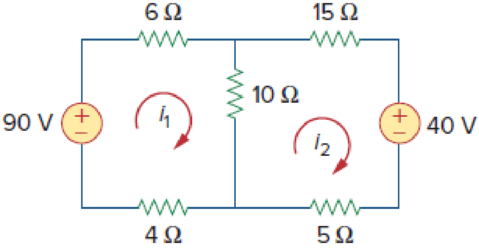
Figure 3.19
For Practice Prob. 3.5.
Calculate the mesh currents i1 and i2 of the circuit of Fig. 3.19.
Answer: i1 = 4.6 A, i2 = 200 mA.
Expert Solution & Answer

Trending nowThis is a popular solution!

Students have asked these similar questions
3.7 Apply nodal analysis to solve for Vx in the circuit of Figure 3.56
3.11 Find Vo and the power dissipated in all the resistors in the circuit of Figure 3.60
3.13 Using Nodal analysis , determine Vo in the circuit in Figure 3.61
NOTLE
UNTVERSTTY
Babylon university
Biomedical engineering department
Electric Circuits fundamentals
Practice problem 3.4: Use mesh analysis to determine i1, i2, and iz in Figure shown below.
U8:
Answer: i = 3.474 A, i2 = 0.4737 A, i3 = 1.1052 A.
A9
neerin
Practice problem 3.2: Find v and i in
eircuit in Figure below.
Answer: -0.2 V, 1.4 A.
3 V
42
7 V
METHODS OF ANALYSIS
LECTURER: ALI SHABAAN 7
CHAPTER 3
Biomediča
Chapter 3 Solutions
Fundamentals of Electric Circuits
Ch. 3.2 - Figure 3.4 For Practice Prob. 3.1. Obtain the node...Ch. 3.2 - Figure 3.6 For Practice Prob. 3.2. Find the...Ch. 3.3 - Figure 3.11 For Practice Prob. 3.3. Find v and i...Ch. 3.3 - Figure 3.14 For Practice Prob. 3.4. Find v1, v2,...Ch. 3.4 - Practice Problem 3.5 Figure 3.19 For Practice...Ch. 3.4 - Practice Problem 3.6 Figure 3.21 For Practice...Ch. 3.5 - Practice Problem 3.7 Figure 3.25 For Practice...Ch. 3.6 - By inspection, obtain the node-voltage equations...Ch. 3.6 - By inspection, obtain the mesh-current equations...Ch. 3.8 - For the circuit in Fig. 3.33, use PSpice to find...
Ch. 3.8 - Use PSpice to determine currents i1, i2, and i3 in...Ch. 3.9 - For the transistor circuit in Fig. 3.42, let =...Ch. 3.9 - The transistor circuit in Fig. 3.45 has = 80 and...Ch. 3 - At node 1 in the circuit of Fig. 3.46, applying...Ch. 3 - Figure 3.46 For Review Questions 3.1 and 3.2 In...Ch. 3 - For the circuit in Fig. 3.47, v1 and v2 are...Ch. 3 - Figure 3.47 For Review Questions 3.3 and 3.4....Ch. 3 - The circuit i in the circuit of Fig. 3.48 is:...Ch. 3 - Figure 3.48 For Review Questions 3.5 and 3.6....Ch. 3 - In the circuit of Fig. 3.49, current i1 is: (a)4 A...Ch. 3 - Figure 3.49 For Review Questions 3.7 and 3.8....Ch. 3 - The PSpice part name for a current-controlled...Ch. 3 - Which of the following statements are not true of...Ch. 3 - Using Fig. 3.50, design a problem to help other...Ch. 3 - For the circuit in Fig. 3.51, obtain v1 and v2....Ch. 3 - Find the currents I1 through I4 and the voltage vo...Ch. 3 - Given the circuit in Fig. 3.53, calculate the...Ch. 3 - Obtain vo in the circuit of Fig. 3.54. Figure 3.54...Ch. 3 - Solve for V1 in the circuit of Fig. 3.55 using...Ch. 3 - Apply nodal analysis to solve for Vx in the...Ch. 3 - Using nodal analysis, find vo in the circuit of...Ch. 3 - Determine Ib in the circuit in Fig. 3.58 using...Ch. 3 - Prob. 10PCh. 3 - Find Vo and the power dissipated in all the...Ch. 3 - Using nodal analysis, determine Vo in the circuit...Ch. 3 - Calculate v1 and v2 in the circuit of Fig. 3.62...Ch. 3 - Using nodal analysis, find vo in the circuit of...Ch. 3 - Apply nodal analysis to find io and the power...Ch. 3 - Determine voltages v1 through v3 in the circuit of...Ch. 3 - Prob. 17PCh. 3 - Determine the node voltages in the circuit in Fig....Ch. 3 - Use nodal analysis to find v1, v2 and v3 in the...Ch. 3 - For the circuit in Fig. 3.69, find v1, v2, and v3...Ch. 3 - For the circuit in Fig. 3.70, find v1 and v2 using...Ch. 3 - Determine v1 and v2 in the circuit of Fig. 3.71....Ch. 3 - Use nodal analysis to find Vo in the circuit of...Ch. 3 - Use nodal analysis and MATLAB to find Vo in the...Ch. 3 - Use nodal analysis along with MATLAB to determine...Ch. 3 - Calculate the node voltages v1, v2, and v3 in the...Ch. 3 - Use nodal analysis to determine voltages v1, v2,...Ch. 3 - Use MATLAB to find the voltages at nodes a, b, c,...Ch. 3 - Use MATLAB to solve for the node voltages in the...Ch. 3 - Using nodal analysis, find vo and io in the...Ch. 3 - Find the node voltages for the circuit in Fig....Ch. 3 - Obtain the node voltages v1, v2, and v3 in the...Ch. 3 - Which of the circuits in Fig. 3.82 is planar? For...Ch. 3 - Determine which of the circuits in Fig. 3.83 is...Ch. 3 - Figure 3.54 For Prob. 3.5. Rework Prob. 3.5 using...Ch. 3 - Use mesh analysis to obtain ia, ib, and ic in the...Ch. 3 - Using nodal analysis, find vo in the circuit of...Ch. 3 - Apply mesh analysis to the circuit in Fig. 3.85...Ch. 3 - Using Fig. 3.50 from Prob. 3.1, design a problem...Ch. 3 - Prob. 40PCh. 3 - Apply mesh analysis to find i in Fig. 3.87. Figure...Ch. 3 - Using Fig. 3.88, design a problem to help students...Ch. 3 - Prob. 43PCh. 3 - Prob. 44PCh. 3 - Prob. 45PCh. 3 - Calculate the mesh currents i1 and i2 in Fig....Ch. 3 - Rework Prob. 3.19 using mesh analysis. Use nodal...Ch. 3 - Prob. 48PCh. 3 - Find vo and io in the circuit of Fig. 3.94. Figure...Ch. 3 - Prob. 50PCh. 3 - Apply mesh analysis to find vo in the circuit of...Ch. 3 - Use mesh analysis to find i1, i2 and i3 in the...Ch. 3 - Prob. 53PCh. 3 - Find the mesh currents i1, i2, and i3 in the...Ch. 3 - In the circuit of Fig. 3.100, solve for I1, I2,...Ch. 3 - Determine v1 and v2 in the circuit of Fig. 3.101....Ch. 3 - In the circuit of Fig. 3.102, find the values of...Ch. 3 - Find i1, i2, and i3 in the circuit of Fig. 3.103....Ch. 3 - Rework Prob. 3.30 using mesh analysis. Using nodal...Ch. 3 - Prob. 60PCh. 3 - Calculate the current gain iois in the circuit of...Ch. 3 - Find the mesh currents i1, i2, and i3 in the...Ch. 3 - Find vx and ix in the circuit shown in Fig. 3.107....Ch. 3 - Find vo and io in the circuit of Fig. 3.108.Ch. 3 - Use MATLAB to solve for the mesh currents in the...Ch. 3 - Write a set of mesh equations for the circuit in...Ch. 3 - Obtain the node-voltage equations for the circuit...Ch. 3 - Prob. 68PCh. 3 - For the circuit shown in Fig. 3.113, write the...Ch. 3 - Write the node-voltage equations by inspection and...Ch. 3 - Write the mesh-current equations for the circuit...Ch. 3 - Prob. 72PCh. 3 - Write the mesh-current equations for the circuit...Ch. 3 - By inspection, obtain the mesh-current equations...Ch. 3 - Use PSpice or MultiSim to solve Prob. 3.58....Ch. 3 - Use PSpice or MultiSim to solve Prob. 3.27....Ch. 3 - Solve for V1 and V2 in the circuit of Fig. 3.119...Ch. 3 - Solve Prob. 3.20 using PSpice or MultiSim. 3.20...Ch. 3 - Prob. 79PCh. 3 - Find the nodal voltages v1 through v4 in the...Ch. 3 - Use PSpice or MultiSim to solve the problem in...Ch. 3 - If the Schematics Netlist for a network is as...Ch. 3 - The following program is the Schematics Netlist of...Ch. 3 - Prob. 84PCh. 3 - An audio amplifier with a resistance of 9 ...Ch. 3 - Prob. 86PCh. 3 - For the circuit in Fig. 3.123, find the gain...Ch. 3 - Determine the gain vo/vs of the transistor...Ch. 3 - For the transistor circuit shown in Fig. 3.125,...Ch. 3 - Calculate vs for the transistor in Fig. 3.126...Ch. 3 - Prob. 91PCh. 3 - Prob. 92PCh. 3 - Rework Example 3.11 with hand calculation. In the...
Knowledge Booster


Learn more about
Need a deep-dive on the concept behind this application? Look no further. Learn more about this topic, electrical-engineering and related others by exploring similar questions and additional content below.Similar questions
- gineerin ww Babylon university Biomedical engineering department Electric Circuits fundamentals Practice problem 3.4: Use mesh analysis to determine i1, i2, and i3 in Figure shown below. Answer: i = 3.474 A, i2 = 0.4737 A, i3 = 1.1052 A. %3D %3D 20: 6 V 3A 10 amaque noarrow_forwardExample: In the circuit of Fig. 3.39, use resistance combination methods and current division to find 1₁, 12, and V3. Answer: 100mA, 50mA, 0.8V. Dr. Firas Obeidat-Philadelphia University 120 mA 1250 500 w 202 W 400 + 200> a> 14arrow_forwardQ3) A) Find Ras for the circuit shown in Figure 3. 50 Figure 3 B) For the circuit shown in Figure 4, use the superposition theorem, the voltage divider rule and the current divider rule to find in. 30 sn Ov 2 V Figure 4arrow_forward
- Determine a valuc for the voltage vas labeled in the circuit of Fig 3.70, and compute the power supplied by the two current sources -2A 100ZR, 3A( R:arrow_forwardPART 1: In this part, you will determine the Thevenin equivalent circuit parameters through computation. a. Determine the Thevenin equivalent circuit of Figure 3.1 between nodes A and B and record all parameters in Table 3.1 under the Calculated Value column. 752 1502 A 5V (+ 2202 4702 Figure 3.1: Determining the Thevenin Equivalent Circuit Calculated Value Vih (V) Isc (mA) Rth (2) Just the calculated value B.arrow_forward3.25. Plot the currents flowing through R1 and Di as a function of Vin for the circuits of Fig. 3.77. Assume constant-voltage diode model.arrow_forward
- Example 3.4 (b) Calculate the value of the shunt resistors for the circuit shown below. Rm = 1k2 Im Rc Rp Ra 100 mA 1 A 10 mA Fig. 3.4(b) For Example 3.4(b)arrow_forwardH.W. 3.1: Obtain the node voltages in the circuit in Figure below. Answer: Vi =-2 V, v2 =-14 V. 62 ww 1 1A O 4A H.W. 3.2: For the circuit in Figure below, obtain vVjand v2. Answer: Vi = 45 V, v2 = 42 V ww 6 A 10 2 4Ω ξ O 3A H.W. 3.3: Given the circuit in Figure below, calculate the currents i through i4. Answer: i = 4 A, iz = 2 A 2A iz = 1 A, i4 = 2 A 4 A 5Ωξ 10Ω 10Ω 5A H.W. 3.4: Calculate vo in the circuit in Figure below using nodal analysis. Answer: vo = 3.652 V 32 ww 12 V 8Ω 2v 1 H.W. 3.5: Find i, in the circuit in Figure below using nodal analysis. 12 Answer: io =-4 A ww 2i, 20 4Ωarrow_forwardExample 3.4 (b) Calculate the value of the shunt resistors for the circuit shown below. Rm = 1k2 Im Rc Rp Ra ww 100 mA 1 A 10 mA Fig. 3.4(b) For Example 3.4(b)arrow_forward
- Practice problem 3.2: Find v and i in the eircuit in Figure below. Answer: -0.2 V, 1.4 A. 3 V mediča 7Varrow_forwardUse mesh analysis and solve for for the following a. Mesh currents i1 b. mesh current i2 c. Mesh current i13 81V 6Ω www r1 12 r4 9A i 602 6A i1 129 ww r2 13r3 30 3Ωarrow_forward1st Stage! FundamentaisS Of Electrical Engineering Chapter 3- Kirchhoff's laws 3.3 Homework: 1- Use KCL to obtain currents i,, i2, and iz in the circuit shown in below figure. 12 mA 8 mA i3 2- Find il, i2, and i3 in the circuit in Figure below.arrow_forward
arrow_back_ios
SEE MORE QUESTIONS
arrow_forward_ios
Recommended textbooks for you
 Introductory Circuit Analysis (13th Edition)Electrical EngineeringISBN:9780133923605Author:Robert L. BoylestadPublisher:PEARSON
 Delmar's Standard Textbook Of ElectricityElectrical EngineeringISBN:9781337900348Author:Stephen L. HermanPublisher:Cengage Learning
 Programmable Logic ControllersElectrical EngineeringISBN:9780073373843Author:Frank D. PetruzellaPublisher:McGraw-Hill Education
 Fundamentals of Electric CircuitsElectrical EngineeringISBN:9780078028229Author:Charles K Alexander, Matthew SadikuPublisher:McGraw-Hill Education
 Electric Circuits. (11th Edition)Electrical EngineeringISBN:9780134746968Author:James W. Nilsson, Susan RiedelPublisher:PEARSON
 Engineering ElectromagneticsElectrical EngineeringISBN:9780078028151Author:Hayt, William H. (william Hart), Jr, BUCK, John A.Publisher:Mcgraw-hill Education,
Introductory Circuit Analysis (13th Edition)
Electrical Engineering
ISBN:9780133923605
Author:Robert L. Boylestad
Publisher:PEARSON
Delmar's Standard Textbook Of Electricity
Electrical Engineering
ISBN:9781337900348
Author:Stephen L. Herman
Publisher:Cengage Learning
Programmable Logic Controllers
Electrical Engineering
ISBN:9780073373843
Author:Frank D. Petruzella
Publisher:McGraw-Hill Education
Fundamentals of Electric Circuits
Electrical Engineering
ISBN:9780078028229
Author:Charles K Alexander, Matthew Sadiku
Publisher:McGraw-Hill Education
Electric Circuits. (11th Edition)
Electrical Engineering
ISBN:9780134746968
Author:James W. Nilsson, Susan Riedel
Publisher:PEARSON
Engineering Electromagnetics
Electrical Engineering
ISBN:9780078028151
Author:Hayt, William H. (william Hart), Jr, BUCK, John A.
Publisher:Mcgraw-hill Education,
Mesh Current Problems in Circuit Analysis - Electrical Circuits Crash Course - Beginners Electronics; Author: Math and Science;https://www.youtube.com/watch?v=DYg8B-ElK0s;License: Standard Youtube License