
Concept explainers
Videos
Find the power dissipated by each resistor in the circuit.
Answer to Problem 36E
The power dissipated by
Explanation of Solution
Calculation:
The circuit diagram is redrawn as shown in Figure 1.
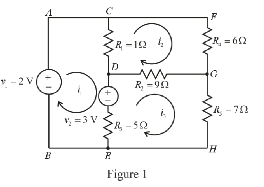
Refer to the redrawn Figure 1
Apply KVL in the mesh
Here,
Apply KVL in the mesh
Here,
Apply KVL in the mesh
Here,
The expression for the power dissipated by the resistor is as follows.
Here,
The current flowing through the
Here,
The current flowing through the
Here,
The current flowing through the
Here,
Refer to the redrawn Figure 1.
Substitute
Substitute
Substitute
Rearrange the equation (8), (9) and (10).
The equations so formed can be written in matrix form as,
Therefore, by Cramer’s rule,
The determinant of coefficient matrix is as follows,
The 1st determinant is as follows.
The 2nd determinant is as follows.
The 3rd determinant is as follows.
Simplify for
Simplify for
Simplify for
Substitute
Substitute
Substitute
Substitute
Substitute
Substitute
Substitute
Substitute
Conclusion:
Thus, the power dissipated by
Want to see more full solutions like this?
Chapter 4 Solutions
Loose Leaf for Engineering Circuit Analysis Format: Loose-leaf


- Question: 4.15 For the circuit in Fig. 4.83arrow_forward1. Two identical batteries are available. If the batteries are connected in series and a voltmeter is used to measure its terminal voltage, the voltmeter reads 18 V. If the batteries are connected in series to supply power to load R, R receives 6 A. If the batteries are connected in parallel to supply power to the same load R, R receives 10/3 A Find the Emf (E) and internal resistance (r) of each battery and the value of R.arrow_forward4. 5. Three resistors, 110, 53 Q, and R, are connected in series with a 24.0-V battery. The total current flowing through the battery is 0.16 A. (a) Find the value of resistance R. (b) Find the potential difference across each resistor. (c) If the voltage of the battery had been greater than 24.0 V, would your answer to part (a) have been larger or smaller? Explain.arrow_forward
- Homework: Calculate v, i, Vz, and iz in the circuit of the following figure. 4.4 ww AZIarrow_forwardQ4. In the meters shown below, if you have to choose them based on their abilities which is independent of time then analyze and justify your selection for each instrument. Discuss them in detail. Meter 1 Meter 2 Meter 3 mA 600 400 200 1000 AC 1200 AMPERES Meter 4 Meter 5arrow_forwardQ5 Draw the output voltage waveform for each circuit in Fig. 4.30 with respect the input. Show voltage levels. +1 V +1 V 0- -I V +2 V Vunmuy = 18 V Vrtmna = 110 V %3D -2 V (a) (b)arrow_forward
- Ohmmeters are used to measure resistances over a wide range from a few milliohms up to 50 MQ. Select one: True Falsearrow_forward13. Given the information provided in Fig. 4.81, determine: (a) Ic. (b) VE. (c) VB. (d) R1. 018 V 4.7 kn V - 12 V VE 3.6 kn 1.2 knarrow_forwardA 5-Ohm resistor is in parallel with a 20-Ohm resistor, is supplied by a 32-V dc battery. Calculate the current at the 5-Ohm resistor. O 1.6 A O 4 A O 6.4 A O 8Aarrow_forward
- Required: - Total Resistance - Total Current - Total Voltage - I4 using CDR (current passing through 4 ohms)arrow_forwardFOR THE CIRCUIT IN THE IMAGE Write down the Circuit equations using a) NODE-Voltage METHOD b) MESH METHOD C) DETERMINE ALL THE VOLTAGE AND CURRENTS IN THE CIRCUIT USING EQUATIONS IN a) and b) and Are the results consistent? Explain.arrow_forward4. A battery has an internal resistance of 0.50 and EMF of 2V. When connected in series to a load resistance, the terminal voltage falls to 1.75V. What current is flowing in the circuit, and what is the value of the load resistance? (Show your solution)arrow_forward
 Introductory Circuit Analysis (13th Edition)Electrical EngineeringISBN:9780133923605Author:Robert L. BoylestadPublisher:PEARSON
 Delmar's Standard Textbook Of ElectricityElectrical EngineeringISBN:9781337900348Author:Stephen L. HermanPublisher:Cengage Learning
 Programmable Logic ControllersElectrical EngineeringISBN:9780073373843Author:Frank D. PetruzellaPublisher:McGraw-Hill Education
 Fundamentals of Electric CircuitsElectrical EngineeringISBN:9780078028229Author:Charles K Alexander, Matthew SadikuPublisher:McGraw-Hill Education
 Electric Circuits. (11th Edition)Electrical EngineeringISBN:9780134746968Author:James W. Nilsson, Susan RiedelPublisher:PEARSON
 Engineering ElectromagneticsElectrical EngineeringISBN:9780078028151Author:Hayt, William H. (william Hart), Jr, BUCK, John A.Publisher:Mcgraw-hill Education,