
Concept explainers
Videos
Find the Thévenin equivalent network seen by the capacitor C in Figure P4.76. Use the result and voltage division to determine
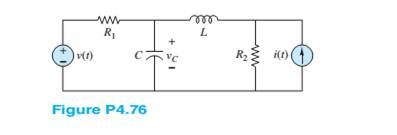
The Thevenin equivalent of the network seen by the capacitor
Answer to Problem 4.76HP
The Thevenin equivalent of the network seen by the capacitor
Explanation of Solution
Calculation:
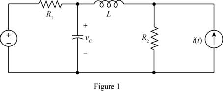
The given diagram is shown in Figure 1
The conversion from
The conversion from
The conversion from
The conversion from
The general form for the expression of voltage is,
The given expression for voltage is given by,
From above and equation (1) the value of angular frequency is given by,
The phasor form of the source voltage is given by,
Substitute
The given expression for current is given by,
The expression for the phasor form of the current is given by
From above and from equation (2) the expression for the phasor form of the current is given by,
The expression to calculate inductive impedance of the inductor is given by,
Substitute
The expression to calculate the capacitive reactance is given by,
Substitute
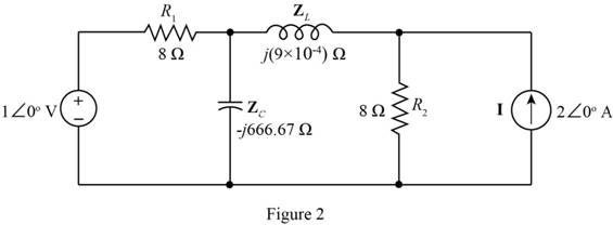
Mark the values and redraw the circuit for the frequency domain.
The required diagram is shown in Figure 2
To obtain the Thevenin equivalent of the circuit, open circuit the capacitor and redraw the circuit.
The required diagram is shown in Figure 3
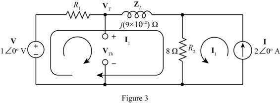
From above figure the value of current
Substitute
Apply KVL to the first loop.
Substitute
Apply KVL to the loop on the left.
Substitute
To determine the Thevenin equivalent impedance, short circuit the voltage source and open circuit the current source and redraw the circuit.
The required diagram is shown in Figure 4
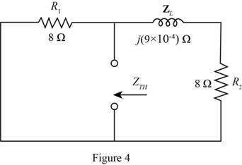
From the above figure, the expression for the Thevenin equivalent impedance is given by,
Mark the values and draw the Thevenin equivalent of the circuit.
The required diagram is shown in Figure 5
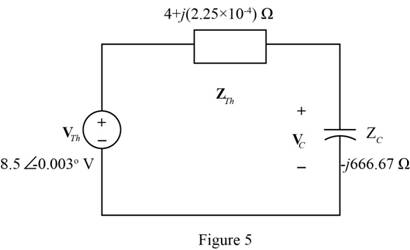
From the above figure the voltage across the capacitor is calculated as,
The general form for the expression of voltage across the capacitor is given by,
From above and from equation (3), the general form of the voltage across the capacitor is given by,
Substitute
Conclusion:
Therefore, the Thevenin equivalent of the network seen by the capacitor
Want to see more full solutions like this?
Chapter 4 Solutions
Principles and Applications of Electrical Engineering


- Determine the equivalent inductance and equivalent current of the inductive circuit in Figure Q4. If L5 is replaced with a capacitor of 0.55 mF, how would it affect the branch current? The alternating Voltage source has an amplitude of 25 Vm.arrow_forwardSince V=12V, C1 = C4 = 2uF, C2 = 4uF, C3 = 1uF in the circuit in the figure, what is the charge (in uC) on the capacitor C4?arrow_forwardIn an R-L-C series circuit a maximum current of 0.5 A is obtained by varying the value of inductance L. The supply voltage is fixed at 230 V, 50 Hz. When maximum current flows through the circuit, the voltage measured across the capacitor is 350 V. What are the values of the circuit parameters? ..arrow_forward
- R 2 0 5e-2 cos(31) 1 H Figure P4.48 If Vg (t) = 5e-2tcos(3t) V, and iL(0-)= -0.3A. a. determine the request voltages and currents. VR(0+)= VL(0+)= İL(0+)= b. On a single graph, draw to scale the waveforms of VG(t) and VL(t). c. expression for iL(t), t>0 urgent in one hour give like handwrittenarrow_forwardA Hay's bridge uses a standard capacitor of C4 = 0.02 mF and operates at a supply frequency of 800 Hz. Balance is achieved when R2 =0.54kn ,R3= 3.8kN, and R4 =100 Q. Find the unknown Resistance R1 and unknown inductance L1. unknown Resistance R1 unknown Inductance L1arrow_forwardQ2: Find the voltage in all capacitor in figure below where the capacitance in uF C1 300 C4 400v 100 C2 C5 60 100arrow_forward
- For the circuit shown in Figure Q2, determine the followi (a) The current in the inductors L1 and L2. (b) The voltage across the capacitors Cl and C2. (c) The total energy stored in the circuit. (d) The total power supplied by the source. 30V II RI -000-m 20mH 1052 50mH 2 R2 2002 300µF -000 30ml 91 300µF CI 600 μF R3 30Ω C3arrow_forwardP4.42. The switch shown in Figure P4.42 has been closed for a long time prior to t=0, then it opens at t=0 and closes again at t=1 s. Find i L (t) for all t. 6H 121 Figure P4.42arrow_forwardA series RL with R = 49-2 and L = 8-H connected across a 24 VDC source for a LONG TIME, how much energy is stored in the inductor? Write the values only (round to four decimal places).arrow_forward
- /Q6 The potential at point P due to Q1 and * :Q2 is = 1x10-12C 0.5 m 0.5 m Q2 = 1x10-12C %3D 50 cm P. 0.01797 V O -0.01271 V O ov O 0.01271 V C 10arrow_forward*P4.61. A dc source is connected to a series RLC circuit by a switch that closes at t = 0, as shown in Figure P4.61. The initial conditions are i(0+) = 0 and vc(0+) = 0. Write the dif- ferential equation for vc(t). Solve for vc(t) given that R = 80 2. t = 0 R 2 mH + V = 50 V i(t) vclt) 5 µF i(0) = 0 vc(0) = 0 Figure P4.61arrow_forwardFor the circuit of Figure 2. Assuming that the capacitor voltage and inductor current are equal to zero at t = 0. a) Determine the expression for all the branch currents and capacitor voltage v(t) b) Obtain the plots of the branch currents and v(t) by creating a MATLAB model in Simulink. Verify the plots by using a MATLAB programarrow_forward
 Introductory Circuit Analysis (13th Edition)Electrical EngineeringISBN:9780133923605Author:Robert L. BoylestadPublisher:PEARSON
 Delmar's Standard Textbook Of ElectricityElectrical EngineeringISBN:9781337900348Author:Stephen L. HermanPublisher:Cengage Learning
 Programmable Logic ControllersElectrical EngineeringISBN:9780073373843Author:Frank D. PetruzellaPublisher:McGraw-Hill Education
 Fundamentals of Electric CircuitsElectrical EngineeringISBN:9780078028229Author:Charles K Alexander, Matthew SadikuPublisher:McGraw-Hill Education
 Electric Circuits. (11th Edition)Electrical EngineeringISBN:9780134746968Author:James W. Nilsson, Susan RiedelPublisher:PEARSON
 Engineering ElectromagneticsElectrical EngineeringISBN:9780078028151Author:Hayt, William H. (william Hart), Jr, BUCK, John A.Publisher:Mcgraw-hill Education,