
Loose Leaf for Engineering Circuit Analysis Format: Loose-leaf
9th Edition
ISBN: 9781259989452
Author: Hayt
Publisher: Mcgraw Hill Publishers
expand_more
expand_more
format_list_bulleted
Videos
Textbook Question
Chapter 4.3, Problem 6P
Determine i1 and i2 in the circuit in Fig. 4.19.
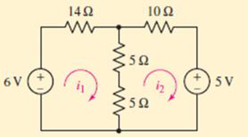
FIGURE 4.19
Ans: +184.2 mA; −157.9 mA
Expert Solution & Answer
Want to see the full answer?
Check out a sample textbook solution
Students have asked these similar questions
The following symbol denotes a p-n type junction diode, where current favors flowing through one
direction than the other (positive current flows from Anode to Cathode side).
p-type
silicon
n-type
silicon
Anode
Cathode
Anode
Cathode
Consider the circuit shown below, where S is the source of alternating positive current, and Load
represents any circuit component that does work when voltage is applied.
A
D4
D,
S
D2
ILoad
В
Using the symbols S, A, B, D1, D2, D3, D4 and arrows, write the order the current passes through
the components when:
a) the current flows from S to A (S→A>..→S)
b) the current flows from S to B (S→B→...→S)
Consider the circuit in Figure 4.
a) Find the Thevenin equivalent of the network connected to the capacitor C1.
b) Find the mathematical equations for the transient behavior of voltage vc(t) and the current ic(t)
following the closing of the switch.
c) Determine the value of voltage vc at t = 100 ms.
%3D
TC LOSE = 0
R1
TK
V1
15V
6K
R2
LIK
R3
C1
R4
0.
3K
Considering the circuit in the following figure, if V1 varies between -20 V and 0 V and Vb=5V, then the current through V1 is (assume ideal diodes):
* D1
D2
4 ko
2 kO
V1
Vo
Vb
-8 V
O a. ((V1 +5)/4) mA for V1 2 -5 V and Zero for V1 s -5 V
O b. ((V1 -5)) mA for V1 s - 5 V and Zero for V1 2 -5 V
Oc. ((V1 +5)/4) mA for V1 s - 5 V and Zero for V1 2 - 5 V
O d. ((V1 +5)/4) mA for V1 s 5 V and Zero for V1 2 5 V
Chapter 4 Solutions
Loose Leaf for Engineering Circuit Analysis Format: Loose-leaf
Ch. 4.1 - For the circuit of Fig. 4.3, determine the nodal...Ch. 4.1 - For the circuit of Fig. 4.5, compute the voltage...Ch. 4.1 - For the circuit of Fig. 4.8, determine the nodal...Ch. 4.2 - For the circuit of Fig. 4.11, compute the voltage...Ch. 4.3 - Determine i1 and i2 in the circuit in Fig. 4.19....Ch. 4.3 - Determine i1 and i2 in the circuit of Fig 4.21....Ch. 4.3 - Determine i1 in the circuit of Fig. 4.24 if the...Ch. 4.4 - Determine the current i1 in the circuit of Fig....Ch. 4.4 - Determine v3 in the circuit of Fig. 4.28. FIGURE...Ch. 4 - Solve the following systems of equations: (a) 2v2 ...
Ch. 4 - (a) Solve the following system of equations:...Ch. 4 - (a) Solve the following system of equations:...Ch. 4 - Correct (and verify by running) the following...Ch. 4 - In the circuit of Fig. 4.35, determine the current...Ch. 4 - Calculate the power dissipated in the 1 resistor...Ch. 4 - For the circuit in Fig. 4.37, determine the value...Ch. 4 - With the assistance of nodal analysis, determine...Ch. 4 - Prob. 9ECh. 4 - For the circuit of Fig. 4.40, determine the value...Ch. 4 - Use nodal analysis to find vP in the circuit shown...Ch. 4 - Prob. 12ECh. 4 - Prob. 13ECh. 4 - Determine a numerical value for each nodal voltage...Ch. 4 - Prob. 15ECh. 4 - Using nodal analysis as appropriate, determine the...Ch. 4 - Prob. 17ECh. 4 - Determine the nodal voltages as labeled in Fig....Ch. 4 - Prob. 19ECh. 4 - Prob. 20ECh. 4 - Employing supernode/nodal analysis techniques as...Ch. 4 - Prob. 22ECh. 4 - Prob. 23ECh. 4 - Prob. 24ECh. 4 - Repeat Exercise 23 for the case where the 12 V...Ch. 4 - Prob. 26ECh. 4 - Prob. 27ECh. 4 - Determine the value of k that will result in vx...Ch. 4 - Prob. 29ECh. 4 - Prob. 30ECh. 4 - Prob. 31ECh. 4 - Determine the currents flowing out of the positive...Ch. 4 - Obtain numerical values for the two mesh currents...Ch. 4 - Use mesh analysis as appropriate to determine the...Ch. 4 - Prob. 35ECh. 4 - Prob. 36ECh. 4 - Find the unknown voltage vx in the circuit in Fig....Ch. 4 - Prob. 38ECh. 4 - Prob. 39ECh. 4 - Determine the power dissipated in the 4 resistor...Ch. 4 - (a) Employ mesh analysis to determine the power...Ch. 4 - Define three clockwise mesh currents for the...Ch. 4 - Prob. 43ECh. 4 - Prob. 44ECh. 4 - Prob. 45ECh. 4 - Prob. 46ECh. 4 - Prob. 47ECh. 4 - Prob. 48ECh. 4 - Prob. 49ECh. 4 - Prob. 50ECh. 4 - Prob. 51ECh. 4 - Prob. 52ECh. 4 - For the circuit represented schematically in Fig....Ch. 4 - The circuit of Fig. 4.80 is modified such that the...Ch. 4 - The circuit of Fig. 4.81 contains three sources....Ch. 4 - Solve for the voltage vx as labeled in the circuit...Ch. 4 - Consider the five-source circuit of Fig. 4.83....Ch. 4 - Replace the dependent voltage source in the...Ch. 4 - After studying the circuit of Fig. 4.84, determine...Ch. 4 - Prob. 60ECh. 4 - Employ LTspice (or similar CAD tool) to verify the...Ch. 4 - Employ LTspice (or similar CAD tool) to verify the...Ch. 4 - Employ LTspice (or similar CAD tool) to verify the...Ch. 4 - Verify numerical values for each nodal voltage in...Ch. 4 - Prob. 65ECh. 4 - Prob. 66ECh. 4 - Prob. 67ECh. 4 - Prob. 68ECh. 4 - Prob. 69ECh. 4 - (a) Under what circumstances does the presence of...Ch. 4 - Referring to Fig. 4.88, (a) determine whether...Ch. 4 - Consider the LED circuit containing a red, green,...Ch. 4 - The LED circuit in Fig. 4.89 is used to mix colors...Ch. 4 - A light-sensing circuit is in Fig. 4.90, including...Ch. 4 - Use SPICE to analyze the circuit in Exercise 74 by...
Knowledge Booster


Learn more about
Need a deep-dive on the concept behind this application? Look no further. Learn more about this topic, electrical-engineering and related others by exploring similar questions and additional content below.Similar questions
- Design a DC voltage source to maintain fixed, stable 15 V, 13.6 V and 12.2 V DC voltages to different loads. In order to realize this request, a transformer having a primer voltage 220 V AC and a seconder voltage 27 V AC (220/27 V AC transformer), some silicon diodes, zener diode and some resistors of 1.5 k2 can be considered in design. a) Draw the network b) Explain the tasks of each component and overall operation in your design. c) Calculate load current and power dissipation for zener diodearrow_forwardLED flashlights use "white" LEDs which have a diode voltage drop of 4.0V. A LED flashlight has the circuit illustrated and will run off several AAA batteries that have a 1.5 VDC rating. a. What is the minimum number of AAA cells needed to turn on the flashlight. b. Would you arrange the batteries in parallel or in series? Vdd R + LED V fritzingarrow_forward!!! !!! 19 M Vx BO Ix In the circuit above, plot lx and IR1 as a function of Vx for two cases: VB = -1.5V and VB = +1.25V. (! D₁ is an ideal Diode ! ) (Upload your answer) R₂ R₁R₁VB D₁ Ideal Ⓡ Parrow_forward
- 4.3 For the circuits shown in Fig. P4.3 using ideal diodes, find the values of the labeled voltages and currents 20- D₁ ☆ K (d) www|11 1 ΚΩ 01/0 C D₂ K KH D₁ ww|11 -0% 1 ΚΩ D₁ 20-4 ▷ K- D₂ e www/11 1 ΚΩ -0%arrow_forwardThis is Circuits. Provide solutionarrow_forwardQ4) The following graph i s hawing the caperitor vu ltoye 0.5MF cupucidoe. Colee lyte the coprsitor, power of a te current fbming (de liverad through et the copecitor und objurbool ) or energy torad in the device, Ye (4), V şlopes are different 3 t(msec) - 1 2 3 4 ( -2. -3arrow_forward
- Subject: Circuits IPlease Help me and show your solution tooarrow_forwardA high voltage Schering-bridge has the following arms a) Standard capacitors: 500 pF and 100 pF b) Variable resistance R4: 1 ohm to 1k-ohm c) C3 = 1nF to 2 uF, R3 = 100 to 1000 ohms: Determine: 2.2.1 The maximum and minimum values of Cx, unknown capacitance that can be measured. 2.2.2 The maximum and minimum loss angle that can be measured at 50 Hz. 2.2.3 The loss angle of the specimen if balance is obtained at 50 Hz with Cx = 200 pF, C3= 10 nF and R4 = 1 k-ohm with a standard capacitor having a capacitance of 500 pF. 2.2.4 The value of the shunt to used with R4 to measure 10 uF.arrow_forward3. Based on an old quiz problem related to half-wave rectifièr design. You may need your design if we have cold weather this winter. for charging your 12 VDC car battery. You are to design a battery eharger for safe operation in a damp garage environment to use RI Current Ling Resor R1 TXI Fuse 12 Vot Car Bater Metal Case Design specifications include: (a) Input is a 110rms VAC. (Vp=110x v2) at 60 Hz from a three wire service that meets the National Electrical Code. (b) Output is a nominal 12 volts VDC at the cathode of the diode. (c) Specify a resistor, R, to limit the maximum battery charging current to 10 amperes into the 12 volt car battery assuming the battery is completely dead (0 volts) when you first connect the charger. A not uncommon occurrence over the last two weeks of sub-zero temperatures. (d) There is no ripple voltage design specification. Explain why this is unnecessary in this application. (e) The battery charger case is metal. (f) Assume a diode with VF= 0.7 V (g)…arrow_forward
- Consider a PV Module with 4 solar PV cells with the Size of each 10cm x 10cm are connected in Parallel. Choose the correct statement for the above PV Module. (Assume necessary data) a. The output voltage is 0.5 V, the output power is 12W b. The output voltage is 2 V, the output power is 12W c. The output voltage is 12 V, the output power is 6W d. The output voltage is 0.5 V, the output power is 6Warrow_forwardA 1) Consider the circuit at right, consisting of two LEDS (one red, one green), which you can model as “practical diodes" with VD= 2.0V (LEDS typically have larger VD's than ordinary Si or Ge diodes). R red green B a) If terminals A and B were connected to a DC source with voltage Vo, what would happen? (Consider applying in both polarities, i.e. +Vo and –Vo, and when VoVD...) b) If the terminals A and B were connected to an AC source with peak voltage VO, what would happen? (Consider both very low frequency: f<~1 Hz – and high-frequency cases.) c) If R = 1 k2, and both diodes have a maximum continuous power dissipation of 0.1 W and a peak inverse voltage VPIV = 20V, what is the maximum DC voltage VDCmax which can be safely applied between A and B?arrow_forward2.2 QUESTIONS ON THIS CHAPTER b.) c.) To forward bias a P-N junction you must : ol 02 □3 04 05 5 To reverse bias a P-N junction you must: ol 02 03 a 2 @ 3 04 05 LESSON B02: THE P-N JUNCTION What is the most evident effect in a forward biased P-N junction? al the current is zero □ 2 @ 3 apply a negative voltage to the P region, and set the N to ground apply a positive voltage to the N region, setting the P to ground apply a positive voltage to the N region and a negative to the P apply a positive voltage to the P region respect to the N region none of the above 04 05 apply a positive voltage between the P region and the N region apply a positive voltage to the P region, setting the N to ground apply a positive voltage to the N region respect to the P regiom apply a negative voltage to the N, setting the P to ground none of the above In a reverse biased P-N junction what is the most evident effect? ol the current is zero exponentially increases the Zener effect the avalanche effect none…arrow_forward
arrow_back_ios
SEE MORE QUESTIONS
arrow_forward_ios
Recommended textbooks for you
 Introductory Circuit Analysis (13th Edition)Electrical EngineeringISBN:9780133923605Author:Robert L. BoylestadPublisher:PEARSON
 Delmar's Standard Textbook Of ElectricityElectrical EngineeringISBN:9781337900348Author:Stephen L. HermanPublisher:Cengage Learning
 Programmable Logic ControllersElectrical EngineeringISBN:9780073373843Author:Frank D. PetruzellaPublisher:McGraw-Hill Education
 Fundamentals of Electric CircuitsElectrical EngineeringISBN:9780078028229Author:Charles K Alexander, Matthew SadikuPublisher:McGraw-Hill Education
 Electric Circuits. (11th Edition)Electrical EngineeringISBN:9780134746968Author:James W. Nilsson, Susan RiedelPublisher:PEARSON
 Engineering ElectromagneticsElectrical EngineeringISBN:9780078028151Author:Hayt, William H. (william Hart), Jr, BUCK, John A.Publisher:Mcgraw-hill Education,
Introductory Circuit Analysis (13th Edition)
Electrical Engineering
ISBN:9780133923605
Author:Robert L. Boylestad
Publisher:PEARSON
Delmar's Standard Textbook Of Electricity
Electrical Engineering
ISBN:9781337900348
Author:Stephen L. Herman
Publisher:Cengage Learning
Programmable Logic Controllers
Electrical Engineering
ISBN:9780073373843
Author:Frank D. Petruzella
Publisher:McGraw-Hill Education
Fundamentals of Electric Circuits
Electrical Engineering
ISBN:9780078028229
Author:Charles K Alexander, Matthew Sadiku
Publisher:McGraw-Hill Education
Electric Circuits. (11th Edition)
Electrical Engineering
ISBN:9780134746968
Author:James W. Nilsson, Susan Riedel
Publisher:PEARSON
Engineering Electromagnetics
Electrical Engineering
ISBN:9780078028151
Author:Hayt, William H. (william Hart), Jr, BUCK, John A.
Publisher:Mcgraw-hill Education,
Mesh Current Problems in Circuit Analysis - Electrical Circuits Crash Course - Beginners Electronics; Author: Math and Science;https://www.youtube.com/watch?v=DYg8B-ElK0s;License: Standard Youtube License