
Applied Statics and Strength of Materials (6th Edition)
6th Edition
ISBN: 9780133840544
Author: George F. Limbrunner, Craig D'Allaird, Leonard Spiegel
Publisher: PEARSON
expand_more
expand_more
format_list_bulleted
Videos
Textbook Question
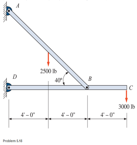
Chapter 5, Problem 5.18P
A bracket is pin connected at points A, B, and D and is subjected to loads, as shown. Calculate the pin reactions. Neglect the weights of the members.
Expert Solution & Answer

Trending nowThis is a popular solution!

Learn your wayIncludes step-by-step video

schedule10:04
Students have asked these similar questions
Calculate the reactions at A and B due to the given point load in Fig
Determine the reactions at A and B for the steel bar and loading shown in Fig. assuming a close fit at both supports before the loads are applied.
Determine the reactions at supports A and B. As part of your solution draw a complete Free Body Diagram. Note that the roller at B is placed on an inclined plane.
Chapter 5 Solutions
Applied Statics and Strength of Materials (6th Edition)
Ch. 5 - through 5.7 Calculate the forces in all members of...Ch. 5 - Calculate the forces in all members of the trusses...Ch. 5 - Calculate the forces in all members of the trusses...Ch. 5 - Calculate the forces in all members of the trusses...Ch. 5 - Calculate the forces in all members of the trusses...Ch. 5 - Calculate the forces in all members of the trusses...Ch. 5 - Calculate the forces in all members of the trusses...Ch. 5 - Determine the forces in members CD, DH, and HI for...Ch. 5 - Determine the forces in members BC, BE, and FE for...Ch. 5 - Determine the forces in members BC, CH, and CG in...
Ch. 5 - For the Howe roof truss shown, determine the...Ch. 5 - Determine the forces in members DE, CE, and BC in...Ch. 5 - Calculate the forces in members BC, BG, and FG for...Ch. 5 - Determine the forces in members CD, BD, BE, and CB...Ch. 5 - A pin-connected A-frame supports a load, as shown....Ch. 5 - Determine the pin reactions at pins A, B, and C in...Ch. 5 - Calculate the pin reactions at each of the pins in...Ch. 5 - A bracket is pin connected at points A, B, and D...Ch. 5 - A pin-connected frame is loaded, as shown....Ch. 5 - The cylinder shown has a mass of 500 kg. Determine...Ch. 5 - A simple frame is pin connected at points A, B,...Ch. 5 - Using the method of sections, determine the forces...Ch. 5 - Using the method of sections, determine the forces...Ch. 5 - through 5.31 Calculate the forces in all members...Ch. 5 - Calculate the forces in all members of the trusses...Ch. 5 - Calculate the forces in all members of the trusses...Ch. 5 - Calculate the forces in all members of the trusses...Ch. 5 - Calculate the forces in all members of the trusses...Ch. 5 - Calculate the forces in all members of the trusses...Ch. 5 - Calculate the forces in all members of the trusses...Ch. 5 - Calculate the forces in all members of the trusses...Ch. 5 - For Problems 5.32 through 5.38, calculate the...Ch. 5 - For Problem 5.32 through 5.38, Calculate the...Ch. 5 - For Problems 5.32 through 5.38, calculate the...Ch. 5 - For Problems 5.32 through 5.38, calculate the...Ch. 5 - For Problem 5.32 through 5.38 , Calculate the...Ch. 5 - For Problems 5.32 through 5.38, calculate the...Ch. 5 - For Problems 5.32 through 5.38, calculate the...Ch. 5 - A pin-connected crane framework is loaded and...Ch. 5 - Calculate the pin reactions at pins A, B, and D in...Ch. 5 - Determine the pin reactions at pins A, B, and C in...Ch. 5 - The wall bracket shown is pin-connected at points...Ch. 5 - Calculate the pin reactions at each of the pins in...Ch. 5 - The A-frame shown is pin-connected at A,B,C, and...Ch. 5 - The tongs shown are used to grip an object. For an...Ch. 5 - A toggle joint is a mechanism by which a...Ch. 5 - In the toggle joint of Problem 5.46 , assume that...Ch. 5 -
Additional Engineering Textbook Solutions
Find more solutions based on key concepts
Determine the magnitude of the moment of the force F = {50i 20j 80k} N about the base line CA of the tripod.
INTERNATIONAL EDITION---Engineering Mechanics: Statics, 14th edition (SI unit)
Use Mohrs circle to determine the normal stress and shear stress acting on the inclined plane AB.
Statics and Mechanics of Materials (5th Edition)
1. In 2001 , the first iPodTM by Apple had a rated battery life of 10 hours (h) to run audio files. The 6th mod...
Thinking Like an Engineer: An Active Learning Approach (4th Edition)
Determine the energy loss that occurs as 40 L/min of water at 10 C flows around a 90 bend in a commercial steel...
Applied Fluid Mechanics (7th Edition)
The 2-Mg truck is traveling at 15 m/s when the brakes on all its wheels are applied, causing it to skid for a d...
Engineering Mechanics: Dynamics (14th Edition)
What parts are included in the vehicle chassis?
Automotive Technology: Principles, Diagnosis, And Service (6th Edition) (halderman Automotive Series)
Knowledge Booster


Learn more about
Need a deep-dive on the concept behind this application? Look no further. Learn more about this topic, mechanical-engineering and related others by exploring similar questions and additional content below.Similar questions
- Compute the magnitudes of the reactions at pin A and the roller at D. Neglect the weight of the body.arrow_forwardFind the magnitude of the pin reaction at B caused by the weight W=80lb. Neglect the weights of the members.arrow_forwardThe uniform ladder of weight W is raised slowly by applying a vertical force P to the rope at A. Show that P is independent of the angle .arrow_forward
- Determine the hinge reactions (in kN) at point B on the beam shown. (Show COMPLETE solutions in all the problems. FREE BODY DIAGRAMS ARE REQUIRED FOR EVERY PROBLEM BEFORE NUMERICAL SOLUTIONS.)arrow_forwardConsider the pin connected frame. Compute for the reactions at the supports and the reactions at the jointsarrow_forwardDetermine the reactions at A and B and the load required Q to hold bar AB in a horizontal position on the smooth inclines shown in Figure 1arrow_forward
- The reactions at G for the truss shown below if the load at B is increased by 6 is ______N.arrow_forwardFor the beam shown below:Draw the free body diagram showing the reactions for each type of supportsknowing that the support on the left is a roller and on the right is a pinarrow_forwardThe A-frame shown is pin-connected at A, B, C, and D. The surface at E is level and frictionless. Calculate the reaction at E and the reaction components at the pins. - Draw free-body diagram - Solve most simple way, save yourself time - Write out all stepsarrow_forward
arrow_back_ios
arrow_forward_ios
Recommended textbooks for you
 International Edition---engineering Mechanics: St...Mechanical EngineeringISBN:9781305501607Author:Andrew Pytel And Jaan KiusalaasPublisher:CENGAGE L
International Edition---engineering Mechanics: St...
Mechanical Engineering
ISBN:9781305501607
Author:Andrew Pytel And Jaan Kiusalaas
Publisher:CENGAGE L
Material Science, Phase Diagrams, Part 1; Author: Welt der Werkstoffe;https://www.youtube.com/watch?v=G83ZaoB3XCc;License: Standard Youtube License