
Mechanics of Materials (MindTap Course List)
9th Edition
ISBN: 9781337093347
Author: Barry J. Goodno, James M. Gere
Publisher: Cengage Learning
expand_more
expand_more
format_list_bulleted
Concept explainers
Videos
Textbook Question
Chapter 5, Problem 5.5.11P
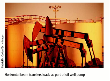
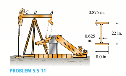
The horizontal beam ABC of an oil-well pump has the cross section shown in the figure. If the vertical pumping force acting at end C is 9 kips and if the distance from the line of action ofthat force to point B is 16 ft, what is the maximum bending stress in the beam due to the pumping force?
Expert Solution & Answer

Trending nowThis is a popular solution!

Students have asked these similar questions
The horizontal beam ABC of an oil-wellpump has the cross section shown in the figure. If thevertical pumping force acting at end C is 9 kips andif the distance from the line of action of that force topoint B is 16 ft, what is the maximum bending stressin the beam due to the pumping force?
Determine the internal normal force and shear force, and the bending moment in the beam at points
C and D. Assume the support at B is a roller. Point C is located just to the right of the 8-kip load. For your
explanation section, complete a FBD of the other side of the beam from the version you did to solve the
problem.
8 kip
40 kip · ft
A
to
to
D
B-
8 ft
8 ft-
-8 ft
The cantilever beam is loaded as shown in the figure. Derive the equations for the
shear force (V) and the bending moment (M) for any location in the beam. Analyze the
beam from the left, taking point A as the origin.
4 kips/ft
8 ft
8ft
What is the moment (in kips-ft) at x = 4.00 ft?
What is the shear force (in kips) at x = 5.50 ft?
What is the moment (in kips-ft) at x = 13.00 ft?
What is the behavior of V equation between points B and C?
What is the behavior of M-diagram between points B and C?
Chapter 5 Solutions
Mechanics of Materials (MindTap Course List)
Ch. 5 - A steel wire with a diameter of d = 1/16 in. is...Ch. 5 - A copper wire having a diameter ofd = 4 mm is bent...Ch. 5 - A 4.75-in, outside diameter polyethylene pipe...Ch. 5 - A cantilever beam AB is loaded by a couple M0at...Ch. 5 - A thin strip of steel with a length of L =19 in....Ch. 5 - A bar of rectangular cross section is loaded and...Ch. 5 - A simply supported beam with a length L = 10 ft...Ch. 5 - A cantilever beam is subjected to a concentrated...Ch. 5 - A thin strip of hard copper (E = 16,000 ksi)...Ch. 5 - A steel wire (E = 200 GPa) of a diameter d = L25...
Ch. 5 - A thin, high-strength steel rule (E = 30 x 10ft...Ch. 5 - A simply supported wood beam AB with a span length...Ch. 5 - Beam ABC has simple supports at A and B and an...Ch. 5 - A simply supported beam is subjected to a in early...Ch. 5 - Each girder of the lift bridge (sec figure) is 180...Ch. 5 - A freight-car axle AS is loaded approximately as...Ch. 5 - A seesaw weighing 3 lb/ft of length is occupied by...Ch. 5 - During construction of a highway bridge, the main...Ch. 5 - The horizontal beam ABC of an oil-well pump has...Ch. 5 - A railroad tie (or sleeper) is subjected to two...Ch. 5 - A fiberglass pipe is lifted by a sling, as shown...Ch. 5 - A small dam of height h = 2.0 m is constructed of...Ch. 5 - Determine the maximum tensile stress (7, (due to...Ch. 5 - Determine the maximum bending stress emaxdue to...Ch. 5 - A simple beam A B of a span length L = 24 ft is...Ch. 5 - Determine the maximum tensile stress erand maximum...Ch. 5 - A cantilever beam A3, loaded by a uniform load and...Ch. 5 - A canti lever beam A B of a n isosceles t...Ch. 5 - A cantilever beam, a C12 x 30 section, is...Ch. 5 - A frame ABC travels horizontally with an...Ch. 5 - A beam ABC with an overhang from B to C supports a...Ch. 5 - A cantilever beam AB with a rectangular cross...Ch. 5 - A beam with a T-section is supported and loaded as...Ch. 5 - Consider the compound beam with segments AB and...Ch. 5 - A small dam of a height h = 6 ft is constructed of...Ch. 5 - A foot bridge on a hiking trail is constructed...Ch. 5 - A steel post (E=30×106) having thickness t = 1/8...Ch. 5 - Beam ABCDE has a moment release just right of...Ch. 5 - A simply supported wood beam having a span length...Ch. 5 - A simply supported beam (L = 4.5 m) must support...Ch. 5 - The cross section of a narrow-gage railway bridge...Ch. 5 - A fiberglass bracket A BCD with a solid circular...Ch. 5 - A cantilever beanie B is loaded by a uniform load...Ch. 5 - A simple beam of length L = 5 m carries a uniform...Ch. 5 - A simple beam AB is loaded as shown in the figure....Ch. 5 - A pontoon bridge (see figure) is constructed of...Ch. 5 - A floor system in a small building consists of...Ch. 5 - The wood joists supporting a plank Floor (see...Ch. 5 - A beam ABC with an overhang from B to C is...Ch. 5 - -12 A "trapeze bar" in a hospital room provides a...Ch. 5 - A two-axle carriage that is part of an over head...Ch. 5 - A cantilever beam AB with a circular cross section...Ch. 5 - A propped cantilever beam A BC (see figure) has a...Ch. 5 - A small balcony constructed of wood is supported...Ch. 5 - A beam having a cross section in the form of an un...Ch. 5 - A beam having a cross section in the form of a...Ch. 5 - Determine the ratios of the weights of four beams...Ch. 5 - Prob. 5.6.20PCh. 5 - A steel plate (called a cover ploie) having...Ch. 5 - A steel beam ABC is simply supported at A and...Ch. 5 - A retaining wall 6 ft high is constructed of...Ch. 5 - A retaining wall (Fig. a) is constructed using...Ch. 5 - A beam of square cross section (a = length of each...Ch. 5 - The cross section of a rectangular beam having a...Ch. 5 - A tapered cantilever beam A B of length L has...Ch. 5 - .2 A ligmio.irc ii supported by two vorlical beams...Ch. 5 - Prob. 5.7.3PCh. 5 - Prob. 5.7.4PCh. 5 - Prob. 5.7.5PCh. 5 - A cantilever beam AB with rectangular cross...Ch. 5 - A simple beam ABC having rectangular cross...Ch. 5 - A cantilever beam AB having rectangular cross...Ch. 5 - The shear stresses t in a rectangular beam arc...Ch. 5 - .2 Calculate the maximum shear stress tmaxand the...Ch. 5 - A simply supported wood beam is subjected to...Ch. 5 - A simply supported wood beam with overhang is...Ch. 5 - Two wood beams, each of rectangular cross section...Ch. 5 - A cantilever beam of length L = 2 m supports a...Ch. 5 - A steel beam of length L = 16 in. and...Ch. 5 - A beam of rectangular cross section (width/) and...Ch. 5 - A laminated wood beam on simple supports (figure...Ch. 5 - A laminated plastic beam of square cross section...Ch. 5 - A wood beam AB on simple supports with span length...Ch. 5 - A simply supported wood beam of rectangular cross...Ch. 5 - A square wood platform is 8 ft × 8 ft in area and...Ch. 5 - A wood beam ABC with simple supports at A and B...Ch. 5 - A wood pole with a solid circular cross section (d...Ch. 5 - A simple log bridge in a remote area consists of...Ch. 5 - A vertical pole consisting of a circular tube of...Ch. 5 - A circular pole is subjected to linearly varying...Ch. 5 - A sign for an automobile service station is...Ch. 5 - A steel pipe is subjected to a quadratic...Ch. 5 - -1 through 5.10-6 A wide-flange beam (see figure)...Ch. 5 - -1 through 5.10-6 A wide-flange beam (see figure)...Ch. 5 - -1 through 5.10-6 A wide-flange beam (see figure)...Ch. 5 - -1 through 5.10-6 A wide-flange beam (see figure)...Ch. 5 - -1 through 5.10-6 A wide-flange beam (see figure)...Ch. 5 - -1 through 5.10-6 A wide-flange beam (see figure)...Ch. 5 - A cantilever beam AB of length L = 6.5 ft supports...Ch. 5 - A bridge girder A B on a simple span of length L =...Ch. 5 - A simple beam with an overhang supports a uniform...Ch. 5 - A hollow steel box beam has the rectangular cross...Ch. 5 - A hollow aluminum box beam has the square cross...Ch. 5 - The T-beam shown in the figure has cross-sectional...Ch. 5 - Calculate the maximum shear stress tmax. in the...Ch. 5 - A prefabricated wood I-beam serving as a floor...Ch. 5 - A welded steel gird crhaving the erass section...Ch. 5 - A welded steel girder having the cross section...Ch. 5 - A wood box beam is constructed of two 260 mm × 50...Ch. 5 - A box beam is constructed of four wood boards as...Ch. 5 - Two wood box beams (beams A and B) have the same...Ch. 5 - A hollow wood beam with plywood webs has the...Ch. 5 - A beam of a T cross section is formed by nailing...Ch. 5 - The T-beam shown in the figure is fabricated by...Ch. 5 - A steel beam is built up from a W 410 × 85 wide...Ch. 5 - The three beams shown have approximately the same...Ch. 5 - Two W 310 × 74 Steel wide-flange beams are bolted...Ch. 5 - A pole is fixed at the base and is subjected to a...Ch. 5 - A solid circular pole is subjected to linearly...Ch. 5 - While drilling a hole with a brace and bit, you...Ch. 5 - An aluminum pole for a street light weighs 4600 N...Ch. 5 - A curved bar ABC having a circular axis (radius r...Ch. 5 - A rigid Trame ABC is formed by welding two steel...Ch. 5 - A palm tree weighing 1000 lb is inclined at an...Ch. 5 - A vertical pole of aluminum is fixed at the base...Ch. 5 - Because of foundation settlement, a circular tower...Ch. 5 - A steel bracket of solid circular cross section is...Ch. 5 - A cylindrical brick chimney of height H weighs w =...Ch. 5 - A flying but tress transmit s a load P = 25 kN,...Ch. 5 - A plain concrete wall (i.e., a wall with no steel...Ch. 5 - A circular post, a rectangular post, and a post of...Ch. 5 - Two cables, each carrying a tensile force P = 1200...Ch. 5 - Prob. 5.12.16PCh. 5 - A short column constructed of a W 12 × 35...Ch. 5 - A short column with a wide-flange shape is...Ch. 5 - A tension member constructed of an L inch angle...Ch. 5 - A short length of a C 200 × 17.1 channel is...Ch. 5 - The beams shown in the figure are subjected to...Ch. 5 - The beams shown in the figure are subjected to...Ch. 5 - A rectangular beam with semicircular notches, as...Ch. 5 - A rectangular beam with semicircular notches, as...Ch. 5 - A rectangular beam with notches and a hole (see...
Knowledge Booster


Learn more about
Need a deep-dive on the concept behind this application? Look no further. Learn more about this topic, mechanical-engineering and related others by exploring similar questions and additional content below.Similar questions
- The simple beam ACE shown in the figure is subjected to a triangular load of maximum intensity q0= 200 lb/ft at a = 8 ft and a concentrated moment M = 400 Ib-ft at A. Draw the shear-force and bending-moment diagrams for this beam, Find the value of distanced that results in the maximum moment occurring at L/2. Draw the shear-force and bending-moment diagrams for this case. Find the value of distance a for which Mmaxis the largest possible value.arrow_forward1. 2. 10 mm 10 mm 3. 5 mm 100 mm A beam section as shown in the sketch is subjected to a bendingmoment of Mx = 4 kN.m and a shear force of V = 2.5KN. 50 mm 100 mm Calculate the position of the centroid and the the second moment of area of the section about the sentroid horizontally. Draw the bending stress distribution through the height of the beam by calculating the bending stress at the critical positions Draw the shear stress distribution trough the height of the beam by calculating the shear stress below the flanges and at the centroid. 4. Draw the stress condition below the flanges, at the centroid and at the top and bottom of the beam.(7) 5. Draw the shearflow through the section. Show calculationsarrow_forward3 For the beam shown, find the reactions at the supports and plot the shear-force and bending-moment diagrams. V = 9 kN, V2 = 9 kN, V3 = 200 mm, and V4 = 1100 mm. ATAT-V3 Provide values at all key points shown in the given shear-force and bending-moment diagrams. X (mm) B A = B = C = D = E= F= P = Q = E * KN * KN * KN × KN KN x KN ✩ kN.mm *kN.mm D 0.00 Reaction force R₁ (left) = In the shear-force and bending-moment diagrams given, +V 0.00 X (mm) 6.3 kN and reaction force R2 (right) = P 11.7 kN. Q 0.00arrow_forward
- The uniform beam with a mass of 500-kg is subjected to three external loads as shown in the figure. Draw the shear force and bending moment diagramsarrow_forwardDraw the Shear force diagram & Bending moment diagram for the cantilever beam as shown in figure, mark the salient points in the diagram. Neglect the self-weight of the beam, where F1 =30 N, F2=60N, F3 =60 N, F4 =80N, a =3 m, b=1 m, c=5 m, d=4 m The reaction at the fixed support "A" (unit in N)=_____________ Answer for part 1 (ii) Shear force at the point "A" (Unit in N) = ________ Answer for part 2 (iii) Shear force at the point "B" (Unit in N) = ________ Answer for part 3 (iv) Shear force at the point "C" (Unit in N) = ________ Answer for part 4 (v) Shear force at the point "D" (Unit in N) = ________ Answer for part 5 (vi) Shear force at the point "E" (Unit in N) = ________ Answer for part 6 (vii) Bending moment at the point "E"(unit in Nm) = ________________ Answer for part 7 (viii) Bending moment at the point "D"(unit in Nm) = ________________ Answer for part 8 (ix) Bending moment at the point "C"(unit in Nm) = ________________ Answer for part 9 (x) Bending moment…arrow_forwardplease answer The shear-force diagram for a beam is shown in the figure. Assuming that no couples act as loads on the beam, determine the forces acting on the beam and draw the bending-moment diagram.arrow_forward
- Determine the shear force V and bending moment M just right of the 6 kN load on the simple beam AB shown in the figure.arrow_forwardFrom the figure shown: X1 q=15 kN/m X2 10m. ********** x1 What is the moment at midspan if X1 = 2 m. Find the distance x₁, if the moment at midspan is zero. 3 Determine the distance x2 so that the maximum moment in the beam is the least possible value.arrow_forwardEstablish the Shear & Moment Equation and Diagram of the loaded beam shown. Consider the Left Body Diagram of each section in establishing the equations. Draw and label the figure properly. Locate the maximum moment and the point of inflection. Figure: 5 kN/m 5 m 12 kN 50 kN-m n D B 2.5m C 2.5 marrow_forward
- Consider a beam with two 60-inch-long rods. both rods have a cross section area of 0.50 in 2 . Find the axial stress in each rod, draw the shear and moment diagrams for the beam, and find the maximum stress in the beam. Please do this without knowing the forces in the rods. it is supposed to be an indeterminate beam. Thank youarrow_forwardDraw the Shear force and bending moment diagram for the beam as shown in figure.arrow_forwardEstablish the Shear & Moment Equation and Diagram of the loaded beam shown. Consider the Left Body Diagram of each section in establishing the equations. Draw and label the figure properly. Locate the maximum moment and the point of inflection. Figure: A 5 kN/m 5m B 2.5 m 12 kN C 2.5 m 50 kN-m Darrow_forward
arrow_back_ios
SEE MORE QUESTIONS
arrow_forward_ios
Recommended textbooks for you
 Mechanics of Materials (MindTap Course List)Mechanical EngineeringISBN:9781337093347Author:Barry J. Goodno, James M. GerePublisher:Cengage Learning
Mechanics of Materials (MindTap Course List)
Mechanical Engineering
ISBN:9781337093347
Author:Barry J. Goodno, James M. Gere
Publisher:Cengage Learning
Fluid Mechanics - Viscosity and Shear Strain Rate in 9 Minutes!; Author: Less Boring Lectures;https://www.youtube.com/watch?v=_0aaRDAdPTY;License: Standard youtube license