
Concept explainers
Videos
5.7 The op amp in Fig. 5.46 has Ri = 100 kΩ, Ro = 100 Ω, A = 100,000. Find the differential voltage vd and the output voltage vo.
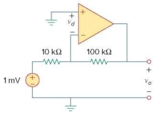
Figure 5.46
For Prob. 5.7.
Calculate the differential voltage
Answer to Problem 7P
The differential voltage
Explanation of Solution
Given data:
Refer Figure 5.46 in the textbook for the op amp circuit.
The open-loop gain A is 100,000,
The input resistance
The output resistance
Calculation:
The equivalent circuit of the the given 741 op amp is drawn and it is shown in Figure 1.
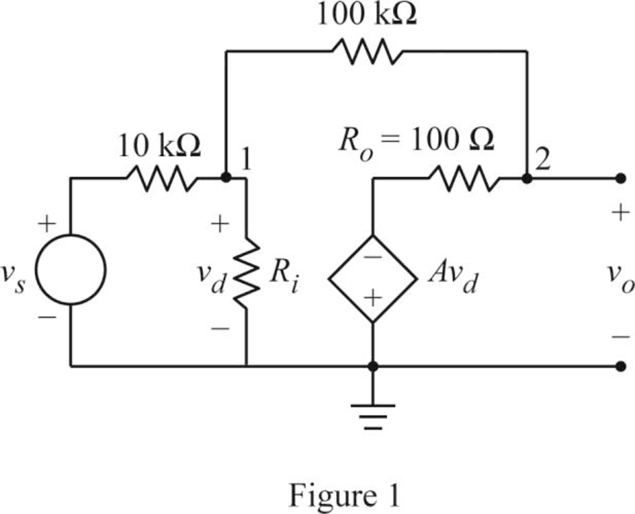
Apply Kirchhoff's current law at node 1 in Figure 1.
Simplify the equation as follows.
From Figure 1, consider the expression for the voltage
Apply Kirchhoff's current law at node 2 in Figure 1.
Substitute 100,000 for A and
Substitute equation (1) in (2).
Simplify the equation as follows.
Substitute 1 mV for
From Figure 1, consider the expression for the output voltage
Substitute 100,000 for A.
Substitute
Conclusion:
Thus, the differential voltage
Want to see more full solutions like this?
Chapter 5 Solutions
Fundamentals of Electric Circuits


- Design an op-amp circuit to yield the relationship shown in each equation. Vo = 8A + 8B – 3C – 12Da.) Rmin = 9KΩb.) Rin = 9KΩarrow_forwardProblem (1): Section 5.3 Ideal Op Amp 5.8 Obtain v, for each of the op amp circuits in Fig. 5.47. 1 mA Figure 5.47 ForProb. 5.8. (a) 2 ΚΩ wwww +1. 9+19 2 V 1 V 10 ΚΩ www 2 ΚΩ Voarrow_forwardDesign an inverting op amp circuit with 6.5 gainarrow_forward
- Design an op-amp circuit to have the following output Vo = 2 - 3 * integrated (Vin dt )arrow_forward5.60 Calculate vo/v; in the op amp circuit of Fig. 5.87. 4 ΚΩ + Vi ΟΙ 5 ΚΩ www Figure 5.87 For Prob. 5.60. 10 ΚΩ + ww 2 ΚΩ 10 ΚΩ + Vo ΤΟarrow_forward+ des y S, ng lues of Section 5.7 Difference Amplifier 5.47 The circuit in Fig. 5.79 is for a difference amplifier. Find v, vo given that v₁ = 1 V and v₂ = 2 V. V₁ + V2 PR 2 ΚΩ ww +1 Figure 5.79 For Prob. 5.47. 2 ΚΩ ww S www C 20 ΚΩ 30 ΚΩ ww 5.48 The circuit in Fig. 5.80 is a differential amplifier driven by a bridge. Find vo. + I + o Vo 10arrow_forward
- 3. Problem 5.29: Determine the voltage gain vo/vi of the following OP Amp circuit R1 R2 R2 R1arrow_forwardCan you please show me what equation you use and calculate: Find the voltage vo assuming the op amp is ideal and the voltages are va = 3, vb = 9, vc = 5, and vd = 6arrow_forwardDetermine Vo and io in the Op-Amp circuit shown in the figure below. www www 62 6k2 6k2 대회 12V 6k2 6k2.arrow_forward
- 2. What op-amp configuration is this circuit? Fill in the value for this circuit to have an Av=5.7. RI= 1k ohm. RI www Vin RF U1 Vout W RI = RF =arrow_forwardGiven the op amp circuit shown in Fig. 5.82, determine the value of R that will make vo = 50 ΚΩ -4 mV o-WWW +1 mV o-WWW 50 ΚΩ www 100 ΚΩ www 100 ΚΩ Ans: Vo' = 10 mV; R = 120 k vo R 40 ΚΩ = 40 mV. O + Voarrow_forwardDesign an ideal non-inverting op amp with a closed-loop gain of Av=10. When vi =0.8v, the current in any resistor is limited to a maximum of 100 micro Amps.arrow_forward
 Introductory Circuit Analysis (13th Edition)Electrical EngineeringISBN:9780133923605Author:Robert L. BoylestadPublisher:PEARSON
 Delmar's Standard Textbook Of ElectricityElectrical EngineeringISBN:9781337900348Author:Stephen L. HermanPublisher:Cengage Learning
 Programmable Logic ControllersElectrical EngineeringISBN:9780073373843Author:Frank D. PetruzellaPublisher:McGraw-Hill Education
 Fundamentals of Electric CircuitsElectrical EngineeringISBN:9780078028229Author:Charles K Alexander, Matthew SadikuPublisher:McGraw-Hill Education
 Electric Circuits. (11th Edition)Electrical EngineeringISBN:9780134746968Author:James W. Nilsson, Susan RiedelPublisher:PEARSON
 Engineering ElectromagneticsElectrical EngineeringISBN:9780078028151Author:Hayt, William H. (william Hart), Jr, BUCK, John A.Publisher:Mcgraw-hill Education,