
Concept explainers
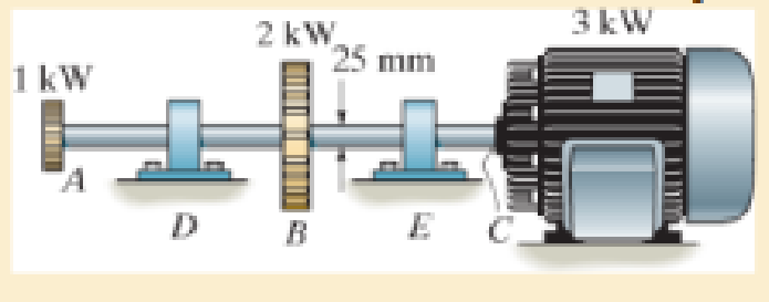
The solid steel shaft AC has a diameter of 25 mm and is supported by smooth bearings at D and E. It is coupled to a motor at C, which delivers 3 kW of power to the shaft while it is turning at 50 rev/s. If gears A and B remove 1 kW and 2 kW, respectively, determine the maximum shear stress in the shaft within regions AB and BC. The shaft is free to turn in its support bearings D and E.

Learn your wayIncludes step-by-step video

Chapter 5 Solutions
Mechanics of Materials
Additional Engineering Textbook Solutions
Engineering Mechanics: Statics
Applied Statics and Strength of Materials (6th Edition)
INTERNATIONAL EDITION---Engineering Mechanics: Statics, 14th edition (SI unit)
Engineering Mechanics: Statics & Dynamics (14th Edition)
Thinking Like an Engineer: An Active Learning Approach (4th Edition)
Automotive Technology: Principles, Diagnosis, and Service (5th Edition)


- The motor produces a torque of T = 20 N # m on gear A. If gear C is suddenly locked so it does not turn, yet B can freely turn, determine the angle of twist of F with respect to E and F with respect to D of the L2-steel shaft, which hasan inner diameter of 30 mm and an outer diameter of 50 mm. Also, calculate the absolute maximum shear stress in the shaft. The shaft is supported on journal bearings at G at H.arrow_forwardThe shaft has an outer diameter of 100 mm and an inner diameter of 80 mm. If it is subjected to the three torques, plot the shear stress distribution along a radial line for the cross section within region CD of the shaft. The smooth bearings at A and B do not resist torque. E 10 kN m B 15 kN m 5 kN-marrow_forwardThe ends and gears connected to the steel shaft (G = 75 GPa) aresubject to the torques shown. Determine the torsional angle of end B with respect to A.The shaft has a diameter of 40 mm.arrow_forward
- The two shafts are made of steel (G=11x106 lb/in2). Each has a diameter of 1 in. , and they are supported by bearings at A, B and C, which allow free rotation. If the support at D is fixed, determine the angle of twist of end A when the torques are applied to the assembly as shown. Torque applied at H of 80 ft lbs, and at G of 40 ft lbs in opposing directions as seen in the figurearrow_forwardThe shaft is made from a solid steel section AB and a tubular portion made of steel and having a brass core. If it is fixed to a rigid support at A, and a torque of T = 50 lb.ft is applied to it at C, determine the rotation angle that occurs at C relative to A and compute the maximum shear stress and maximum shear strain in the brass and steel. Take Gst = 11500 ksi, Gbr = 5600 Ksi. 3 ft 0.5 in. B 1 in. T = 50 lb•ftarrow_forwardThe solid steel shaft is supported by frictionless bearings in D and E. This system is connected to a motor that provides 5 kW of power to the shaft while rotating at w = 75 rpm. If A and B gears get 2 kW and 3 kW respectively, determine the minimum shaft diameter. w rotation speed and safety shear stress τem = 35MPa are known and given in the table with your names below.arrow_forward
- The motor A delivers 7500 kW to the shaft at 3600 rev/min, of which 2500 kW is removed by gear B and 5000 kW is removed by gear C. Determine (a) the maximum shear stress in the shaft; and (b) the angle of twist of end D relative to end A. Use G = 83 GPa for steel, and assume that friction at bearing D is negligible. Show complete solution, and the free body diagram.arrow_forwardThe shaft has an outer diameter of 100 mm and an inner diameter of 80 mm. If it is subjected to the three torques, plot the shear stress distribution along a radial line for the cross section within region CD of the shaft. The smooth bearings at A and B do not resist torque.arrow_forwardQ: Part A: Determine the absolute maximum shear stress in the shaft. Part B: Determine the angle of twist of end EE of the shaft relative to BB. Given: The turbine develops 150 kW of power, which is transmitted to the gears such that CC receives 70% and DD receives 30%. The rotation of the 100-mm diameter A-36 steel shaft is ωomega = 600 rev/min . The journal bearing at EE allows the shaft to turn freely about its axis. The shear modulus of elasticity for A-36 steel is 75 GPa.arrow_forward
- The turbine develops 150 kW of power, which is transmitted to the gears such that C receives 70% and D receives 30%. If the rotation of the 100-mm-diameter A-36 steel shaft is w = 800 rev/ min., determine the absolute maximum shear stress in the shaft and the angle of twist of end E of the shaft relative to B. The journal bearing at E allows the shaft to turn freely about its axis. D 3 m E 4 m 2 marrow_forwardGear B supplies 15 kW of power, while gears A, C and D withdraw 6 kW, 4 kW and 5 kW, respectively. If the shaft is made of steel with the allowable shear stress of Tmax = 75 MPa, and the relative angle of twist between any two gears cannot exceed 0.05 rad, determine the required minimum diameter d of the shaft to the nearest millimeter. The shaft is rotating at 600 rpm. Shear modulus of steel G = 75 MPa| 600 mm 600 mm 600 mmarrow_forwardThe solid 35-mm-diameter shaft is used to transmit the torques applied to the gears. The shaft is made of steel A-36 with E = 200 GPa and G = 75 GPa a. Determine the absolute maximum shear stress on the shaft. b. Determine the angle of twist of the end B with respect to end A. c. The shaft is now change d to a hollowed shaft with an outside diameter of 40 mm. What inner diameter is required to resist the same torque with the same maximum shear stress?arrow_forward
 Elements Of ElectromagneticsMechanical EngineeringISBN:9780190698614Author:Sadiku, Matthew N. O.Publisher:Oxford University Press
 Mechanics of Materials (10th Edition)Mechanical EngineeringISBN:9780134319650Author:Russell C. HibbelerPublisher:PEARSON
 Thermodynamics: An Engineering ApproachMechanical EngineeringISBN:9781259822674Author:Yunus A. Cengel Dr., Michael A. BolesPublisher:McGraw-Hill Education
 Control Systems EngineeringMechanical EngineeringISBN:9781118170519Author:Norman S. NisePublisher:WILEY
 Mechanics of Materials (MindTap Course List)Mechanical EngineeringISBN:9781337093347Author:Barry J. Goodno, James M. GerePublisher:Cengage Learning
 Engineering Mechanics: StaticsMechanical EngineeringISBN:9781118807330Author:James L. Meriam, L. G. Kraige, J. N. BoltonPublisher:WILEY