
Concept explainers
Videos
The cross section of a concrete dam is as shown. For a 1-m-wide dam section determine (a) the resultant of the reaction forces exerted by the ground on the base AB of the dam, (b) the point of application of the resultant of part a, (c) the resultant of the pressure forces exerted by the water on the face BC of the dam.
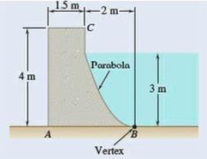
Fig. P5.81
(a)
The reaction forces exerted by the ground on the base of the concrete dam
Answer to Problem 5.81P
The resultant reaction forces acts on the base of the dam is
Explanation of Solution
Given that the width of the dam section
The free-body diagram consists of dam and the triangular section

The length
Write the equation for weight force acts on the dam.
Here, the weight of the dam is
Replace
Here, the thickness of the dam section is
Write the equation for the weight of the dam represented by the weights of its components.
Here, the weight of the dam by the components of fist section is
Substitute
Write the equation for the weight of the dam represented in the triangular section.
Here, the weight of the dam by the components of second section is
Substitute
Write the equation for the weight of the dam represented in the parabola section by the weights of its components.
Here, the weight of the dam by the components of third section is
Substitute
Write the equation of the force pressure exerted by the ground on the base of the dam.
Here, the reaction force exerted on the dam is
Replace
Write the equilibrium equation for the section of dam acts along x axis (Refer Fig 1).
Here, the reaction force exerted by the ground on the base
Write the equilibrium equation for the section of beam acts along y axis and then calculate the reaction force (Refer Fig 1).
Here, the reaction force exerted by the ground on the base
Conclusion:
Substitute
Substitute
Substitute
Therefore, the resultant reaction forces acts on the base of the dam is
(b)
The point of forces acts on the base
Answer to Problem 5.81P
The point in which the forces acts on the base
Explanation of Solution
The distance from the base of the dam to the point
The distance from the base of the dam to the side
The distance from the base of the dam to the point
Write the equilibrium equation for the section on the base
Here, the different section of the dam is represented as
Conclusion:
Substitute
Solve the above equation for
Therefore, the point in which the forces acts on the base
(c)
The resultant pressure force exerted by the water on the face
Answer to Problem 5.81P
The resultant pressure force exerted by the water on the face
Explanation of Solution
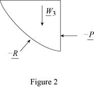
The free body diagram of the water section
Write the equilibrium equation for the s resultant pressure force exerted by the water on the face
Here, the resultant pressure force exerted by the water on the dam is
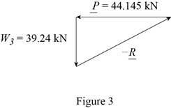
Solve for the angle of resultant force exerted by the water on the dam by using trigonometric relation (Refer fig 3).
Conclusion:
Substitute
Substitute
Therefore, the resultant pressure force exerted by the water on the face
Want to see more full solutions like this?
Chapter 5 Solutions
Vector Mechanics for Engineers: Statics


- Required information Problem 02.003 - Addition of planar forces applied to a hook NOTE: This is a multi-part question. Once an answer is submitted, you will be unable to return to this part. Two forces P and Q are applied as shown at point A of a hook support. ट 20°i 35° Problem 02.003.b - Resultant of forces applied to a hook using the triangle rule Knowing that P = 75 N and Q = 195 N, determine graphically the magnitude and direction of their resultant using the triangle rule. The magnitude of the resultant is The direction of the resultant is 245.8 N. 14.5°arrow_forwardQ.2) If two forces are applied to a rigid body, which have the same magnitude (F) anc the same direction, the resultant force is: (a) 2F (b) F (c) 0 (d) - Farrow_forwardH.W: A frame ABC is supported in part by cable DBE that passes through a frictionless ring at B. Knowing that the tension in the cable is 385 N, determine (a)- the resultant (R) of the forces as a vector which exerted by the cables on the support at D and E, (b)- the angles between R and each of the coordinate axes. Answer: 20 mm 10 mn R= Fan + FRE =-(375 N)i +(455 N)j-(460 N)k E 0, =120.1° « 0, = 52.5° 4 510 mm 400 mm 0. =128.0° 4arrow_forward
- Q.2) A person uses an exercise band with an elastic modulus (spring constant) of 35 lb/ft. They begin the exercise with their arm relaxed in the vertical position (OA), at which point the band is unstretched. The person rotates their arm up to the horizontal position shown, so that their shoulder is at point O and their hand is at point B. Determine the moment exerted by the elastic band on the person's shoulder joint in this position. 24 in B. 24" (F 28 in Carrow_forwardProblem 3.7 The simple structure shown in Fig 3.35 is called a cantilever beam and is one of the fundamental mechanical elements in engineering. A cantilever beam is fixed at one end and free at the other. In Fig. 3.35, the fixed and free ends of the beam are identified as points A and C, respectively. Point B correspondks to the center of gravity of in the beam. Assume that the beam shown has a weight W = 100 N and a length /=1m. A force with magnitude F= 150 N is applied at the free-end of the beam in a direction that makes an angle 0- 45" with the hon zontal. Determine the magnitude and direction of the net moment developed at the fixed-end of the be am, Pr Fig arm the f (a) I th WE ex ind Answer, MA 56 N-m (ccw). Fig. 3.35 A cantuleverlam Fig. 3.37 IPro ype here to searcharrow_forwardPage 115 3.41 Ropes AB and BC are two of the ropes used to support a tent. The two ropes are attached to a stake at B. If the tension in rope AB is 540 N, determine (a) the angle between rope AB and the stake, (b) the projection on the stake of the force exerted by rope AB at point B. Fig. P3.41 and P3.42 3 m A 3 m Z B 1.5 m x D 0.38 m 0.08 m. B 0.16 m Detail of the stake at Barrow_forward
- Q.4) A wooden board is supported by two cables. If the tension in cable AB is 325 lb and the tension in cable AC is 400 lb determine (a) the magnitude of the resultant force exerted at point A, (b) the coordinate direction angles of the resultant force, and (c) the lengths of cables AB and AC.arrow_forwardH.W: A frame ABC is supported in part by cable DBE that passes through a frictionless ring at B. Knowing that the tension in the cable is 385 N, determine (a)- the resultant ( R) of the forees as a vector which exerted by the cables on the support at D and E, (b)- the angles between R and each of the coordinate axes. Answer: 210 ma R= Fan + Fn =-(375 N)i + (455 N)j-(460 N)k e, =120.1° e, = 52.5° 510 m 400 am 0. = 128.0° IB 0marrow_forwardProblem 3: Two forces P and Q are applied as shown at point A of a hook support. Knowing that P=75 N and Q 125 N, determine the magnitude and direction of their resultant. P 2035 Qarrow_forward
- Problem (4.18): A vessel has a length of 60 m, width 12 m and a displacement of 19620 kN. When a eight of294.3 KN is rolled off transversely across the deck through a distance of 6.5 m, the vessel mts through S°. The second moment of area of the water line section about its fore-and-oft axis is 75 per cent of that of the circumscribing rectangle. The center of buoyancy is 2.75 m below the water line. Find: (i) The metacentric height (ii) The position of center of gravity of the vessel. Take specific weight of sea water 10.104 kN/m* [Ans. (i) 1.1145 m (ii) 0.53 m below water surface]arrow_forwardRopes AB and BC are two of the ropes used to support a tent. The two ropes are attached to a stake at B . If the tension in rope AB is 540 N, determine (a) the angle between rope AB and the stake, (b) the projection on the stake of the force exerted by rope AB at point B.arrow_forwardQ1): The cable stays AB and AD help support pole AC. Knowing that the tension is 120 lb in AB and 40 lb in AD. Determine the magnitude and the direction of the resultant of the forces exerted by the stays at A. 10 t sit -6 it Q2): 425 A steel tank is to be positioned in an excavation. Knowing that the magnitude of P is 500 Ib, determine by trigonometry (a) the required angle a if the resultant R of the two forces applied at A is to be vertical, (b) the corresponding magnitude of R.arrow_forward
 Elements Of ElectromagneticsMechanical EngineeringISBN:9780190698614Author:Sadiku, Matthew N. O.Publisher:Oxford University Press
 Mechanics of Materials (10th Edition)Mechanical EngineeringISBN:9780134319650Author:Russell C. HibbelerPublisher:PEARSON
 Thermodynamics: An Engineering ApproachMechanical EngineeringISBN:9781259822674Author:Yunus A. Cengel Dr., Michael A. BolesPublisher:McGraw-Hill Education
 Control Systems EngineeringMechanical EngineeringISBN:9781118170519Author:Norman S. NisePublisher:WILEY
 Mechanics of Materials (MindTap Course List)Mechanical EngineeringISBN:9781337093347Author:Barry J. Goodno, James M. GerePublisher:Cengage Learning
 Engineering Mechanics: StaticsMechanical EngineeringISBN:9781118807330Author:James L. Meriam, L. G. Kraige, J. N. BoltonPublisher:WILEY