
Principles of Foundation Engineering (MindTap Course List)
8th Edition
ISBN: 9781305081550
Author: Braja M. Das
Publisher: Cengage Learning
expand_more
expand_more
format_list_bulleted
Concept explainers
Videos
Textbook Question
Chapter 6, Problem 6.12P
Refer to Problem 6.1. Using Eqs. (6.3) and (6.29), estimate the average stress increase (Δσav) below the center of the loaded area between depths of 3 m and 6 m.
6.1 A flexible circular area is subjected to a uniformly distributed load of 150kN/m2 (Figure 6.2). The diameter of the load area is 2 m. Determine the stress increase in a soil mass at points located 3 m below the loaded area at r = 0. 0.4 m, 0.8 m, and 1 m. Use Boussinesq’s solution.
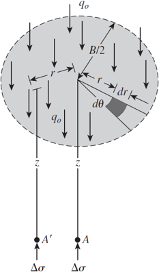
Figure 6.2 Increase in pressure under a uniformly loaded flexible circular area
Expert Solution & Answer
Want to see the full answer?
Check out a sample textbook solution
Students have asked these similar questions
1.A dry sand is known to have an angle of internal friction of 29. A triaxial test is planned, where the confining pressure will be 41 kPa. What is the maximum axial stress, in kPa, (major principal stress) that can be applied? Calculate the value to 1 decimal place. Do not provide units in your answer.
2.A clay soil is subjected to a triaxial test under unconsolidated-undrained conditions. At failure, the major and minor principal stresses are 8401 psf and 4875 psf, respectively. What is the shear strength of this soil if the confining pressure is doubled? Provide your answer in psf with no decimals.
1- A soil profile consisting of three layers is shown in Figure below.
1. Calculate the values of o, u, and o' at points A, B, C, and D. In each case, plot the variations of o, u, and o'
with depth.
2. What is the change in effective stress at point C if:
the water table drops by 2 ft?
а.
b. the water table rises to the surface up to point A?
Layer
Thickness
Soil Parameter
no.
1
H1= 3 ft
YF110 lb/ft³
2
H2= 5 ft
Ysar-120 lb/ft³
H3= 2.5 ft
Ysar-118 lb/ft³
H1
Layer 1
В
Groundwater table
H,
Layer 2
Ha
Layer 3
O Dry sand
Sand
Clay
Rock
3.
7.12 A sand specimen was subjected to a drained shear test using hollow cylin-
der test equipment. Failure was caused by increasing the inside pressure while
keeping the outside pressure constant. At failure, o, = 193 kN/m² and o; =
264 kN/m². The inside and outside radii of the specimen were 40 and 60 mm,
respectively.
(a) Calculate the soil friction angle.
(b) Calculate the axial stress on the specimen at failure.
Chapter 6 Solutions
Principles of Foundation Engineering (MindTap Course List)
Ch. 6 - A flexible circular area is subjected to a...Ch. 6 - Point loads of magnitude 100, 200, and 400 kN act...Ch. 6 - Refer to Figure P6.3. Determine the vertical...Ch. 6 - Refer to Figure P6.4. A strip load of q = 900...Ch. 6 - Refer to Figure 6.6, which shows a flexible...Ch. 6 - Repeat Problem 6.5 with B1 = 4 ft, B2 = 10 ft, L1...Ch. 6 - Use Eq. (6.14) to determine the stress increase ()...Ch. 6 - Prob. 6.8PCh. 6 - Prob. 6.9PCh. 6 - Prob. 6.10P
Knowledge Booster


Learn more about
Need a deep-dive on the concept behind this application? Look no further. Learn more about this topic, civil-engineering and related others by exploring similar questions and additional content below.Similar questions
- Redo Problem 6.12 using Figure 6.15. 6.12 Refer to Problem 6.1. Using Eqs. (6.3) and (6.29), estimate the average stress increase (av) below the center of the loaded area between depths of 3 m and 6 m. 6.1 A flexible circular area is subjected to a uniformly distributed load of 150 kN/m2 (Figure 6.2). The diameter of the load area is 2 m. Determine the stress increase in a soil mass at points located 3 m below the loaded area at r = 0, 0.4 m, 0.8 m, and 1 m. Use Boussinesqs solution. Figure 6.2 Increase in pressure under a uniformly loaded flexible circular areaarrow_forwardFor the same line loads given in Problem 10.8, determine the vertical stress increase, z, at a point located 4 m below the line load, q2. Refer to Figure 10.41. Determine the vertical stress increase, z, at point A with the following values: q1 = 110 kN/m, q2 = 440 kN/m, x1 = 6 m, x2 = 3 m, and z = 4 m. Figure 10.41arrow_forwardRefer to Figure 8.13. The magnitude of the line load q is 45 kN/m. Calculate and plot the variation of the vertical stress increase, between the limits of x = 10 m and x = +10 m, given z = 4 m. FIG. 8.13 Line load over the surface of a semiinfinite soil massarrow_forward
- Use Eq. (6.14) to determine the stress increase () at z = 10 ft below the center of the area described in Problem 6.5. 6.5 Refer to Figure 6.6, which shows a flexible rectangular area. Given: B1 = 4 ft, B2 = 6 ft, L1, = 8 ft, and L2 = 10 ft. If the area is subjected to a uniform load of 3000 lb/ft2, determine the stress increase at a depth of 10 ft located immediately below point O. Figure 6.6 Stress below any point of a loaded flexible rectangular areaarrow_forwardRefer to the flexible loaded rectangular area shown in Figure 10.47. Using Eq. (10.36), determine the vertical stress increase below the center of the loaded area at depths z = 3, 6, 9, 12, and 15 m. Figure 10.47arrow_forwardA soil profile is shown in figure below. Dry sand 6m Ydry = 16.5 kN/m³ B Groundwater table Saturated sand 13m Ysat = 19.25 kN/m² C Dry sand Saturated sand Clay Calculate the following: a. Effective stress at point A in kPa. b. Effective stress at point B in kPa. c. Effective stress at point C in kPa. 5.arrow_forward
- Q1: A sample was obtained from point A in the submerged clay layer shown below. It was determined that it had: W= 54% G3= 2.78 What is the effective vertical stress at A. h, = 25 m water Saturated clay h, = 15 m Aarrow_forwardA direct shear test, when conducted on a remolded sample of sand, gave the following observations at the time of failure: Normal load = 288 N; shear load = 173 N. The cross-sectional area of the sample = 36 cm2. Determine the minor principal stress in kPa. Pls include fbd.arrow_forwardA soil element is shown in the figure below. 128 kN/m2 32 kN/m 32 kN/m2 162 kN/m2 55 Determine the following: (in kPa) a. Maximum Principal Stress b. Minimum Principal Stress C. Normal Stress on plane AB d. Shear Stress on plane ABarrow_forward
- A dilatometer test (DMT) was conducted in a clay deposit. The water table was located at a depth of 3 mbelow theground surface. At 8 m depth the contact pressure (p1) was 280 kPa and the expansion stress (p2) was 350 kPa.Assume σo = 95 kPa at the 8 m depth and μ = 0.35. Determine (a) Coefficient of at-rest earth pressure Ko,(b) Overconsolidation ratio OCR and (c) Modulus of elasticity Es.arrow_forwardA soil element is shown in Figure 10.34. Determine the following:a. Maximum and minimum principal stressesb. Normal and shear stresses on plane ABUse Eqs. (10.3), (10.4), (10.6), and (10.7).arrow_forwardA clayey soil has a drained angle of friction of 28° and cohesion of 30 kPa. In the triaxial test of the same sample, the maximum shearing stress is 70 kPa.1. Compute the all around pressure for failure to occur. a. 25.62 kPab. 28.62 kPac. 20.51 kPad. 22.68 kPa2. Calculate the normal stress at maximum shear. a. 86.51 kPab. 96.52 kPac. 46..51kPad. 92.68 kPa3. Determine the major principal stress at failure. a. 186.41 kPab. 136.52 kPac. 158.70 kPad. 162.68 kPaarrow_forward
arrow_back_ios
SEE MORE QUESTIONS
arrow_forward_ios
Recommended textbooks for you
 Principles of Foundation Engineering (MindTap Cou...Civil EngineeringISBN:9781305081550Author:Braja M. DasPublisher:Cengage Learning
 Principles of Geotechnical Engineering (MindTap C...Civil EngineeringISBN:9781305970939Author:Braja M. Das, Khaled SobhanPublisher:Cengage Learning
 Fundamentals of Geotechnical Engineering (MindTap...Civil EngineeringISBN:9781305635180Author:Braja M. Das, Nagaratnam SivakuganPublisher:Cengage Learning
 Principles of Foundation Engineering (MindTap Cou...Civil EngineeringISBN:9781337705028Author:Braja M. Das, Nagaratnam SivakuganPublisher:Cengage Learning
Principles of Foundation Engineering (MindTap Cou...
Civil Engineering
ISBN:9781305081550
Author:Braja M. Das
Publisher:Cengage Learning
Principles of Geotechnical Engineering (MindTap C...
Civil Engineering
ISBN:9781305970939
Author:Braja M. Das, Khaled Sobhan
Publisher:Cengage Learning
Fundamentals of Geotechnical Engineering (MindTap...
Civil Engineering
ISBN:9781305635180
Author:Braja M. Das, Nagaratnam Sivakugan
Publisher:Cengage Learning
Principles of Foundation Engineering (MindTap Cou...
Civil Engineering
ISBN:9781337705028
Author:Braja M. Das, Nagaratnam Sivakugan
Publisher:Cengage Learning
Stress Distribution in Soils GATE 2019 Civil | Boussinesq, Westergaard Theory; Author: Gradeup- GATE, ESE, PSUs Exam Preparation;https://www.youtube.com/watch?v=6e7yIx2VxI0;License: Standard YouTube License, CC-BY