
Concept explainers
Videos
The truss shown consists of nine members and is support by a ball-and-socket at B, a short link at C, and two short links at D. (a) Check that this truss is a simple truss, that completely constrained, and that the reactions at its suppo are statically determinate. (b) Determine the force in each member for P = (−1200 N)j and Q = 0.
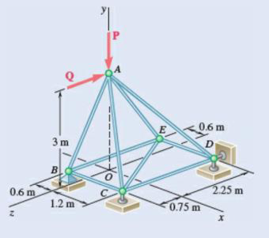
Fig. P6.39
(a)
Verify that the truss is a simple truss, completely constrained, and the reactions at the supports are statically determinate.
Answer to Problem 6.39P
The reactions at supports B, C, and D is
Explanation of Solution
Given information:
The value of the force P is
The value of the force Q is zero.
Calculation:
Show the free-body diagram of the truss as in Figure 1.
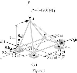
Find the vector coordinates by taking moment about point B.
Equate the coefficients of i to zero.
Equate the coefficients of j to zero.
Equate the coefficients of k to zero.
Substitute 300 N for
Resolve the force components in y-axis.
Substitute 300 N for
The unknown reactions can be calculated with the equilibrium equations. Therefore, the truss is statically determinate, completely constrained and simple truss.
Thus, the reactions at supports B, C, and D is
(b)
Find the force in each member of the truss.
Answer to Problem 6.39P
The force in the member AB is
The force in the member BC is
The force in the member BE is
The force in the member AC is
The force in the member CE is
The force in the member CD is
The force in the member AD is
The force in the member DE is
The force in the member AE is
Explanation of Solution
Show the free-body diagram of the joint B as in Figure 2.
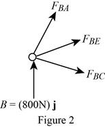
Resolve the force components as follows;
Write the vector value of
Find the scalar quantity of BA using the relation.
Find the force in the member AB as follows;
Substitute
Find the force in the member BC as follows;
Find the force in the member BE as follows;
Equate the coefficients of j to zero.
Equate the coefficients of i to zero.
Substitute –840 N for
Equate the coefficients of k to zero.
Substitute –840 N for
Therefore,
The force in the member AB is
The force in the member BC is
The force in the member BE is
Show the free-body diagram of the joint C as in Figure 3.
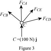
Resolve the force components as follows;
Write the vector value of
Find the scalar quantity of CA using the relation.
Find the force in the member AC as follows;
Substitute
Find the force in the member CB as follows;
Find the force in the member CD as follows;
Write the vector value of
Find the scalar quantity of CE using the relation.
Find the force in the member CE as follows;
Substitute
Equate the coefficients of j to zero.
Equate the coefficients of i to zero.
Substitute –110.6 N for
Equate the coefficients of k to zero.
Substitute –110.6 N for
Therefore,
The force in the member AC is
The force in the member CE is
The force in the member CD is
Show the free-body diagram of the joint D as in Figure 4.
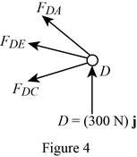
Resolve the force components as follows;
Write the vector value of
Find the scalar quantity of DA using the relation.
Find the force in the member AD as follows;
Substitute
Find the force in the member DC as follows;
Find the force in the member DE as follows;
Equate the coefficients of j to zero.
Equate the coefficients of i to zero.
Substitute –394 N for
Therefore,
The force in the member AD is
The force in the member DE is
Show the free-body diagram of the joint E as in figure 5.
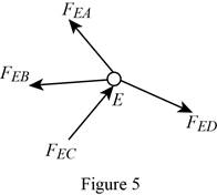
The member AE is not in the xz plane.
Therefore, the force in the member AE is
Want to see more full solutions like this?
Chapter 6 Solutions
Vector Mechanics for Engineers: Statics


- Problem 4: The space truss shown below is supported by ball-and-socket joints at C, D, and E. Determine the force in each member and state whether each member is in tension or compression. (Hint: The support reaction at E acts along the member EB). 2 m 5.m 3 m 3 m 5 m 20 kNarrow_forwardIn the structure shown, force F is applied at point A at an angle of 0 in the direction shown. Pins at G, E, D, B, and C are all frictionless and all members are weightless. For the given values of F and 0 determine: F = 50 N e= 20 deg A G (a) The reactions at points G and E (b) The forces applied to member GDC at points C and D (c) The forces applied to member ABC at point B 70 m 50 m E D B Note: components of forces in x and y directions are enough. 15 m YA 60 m 20m-arrow_forwardPractice Problem 4.4.17: Using the method of joints, calculate the force in each member of the trusses shown. State whether each member is in tension or compression. 6 ft 8 kN A 10 ft 8 kN B 45° 45° 60 E D 8 ftarrow_forward
- In the structure shown, force F is applied at point A at an angle of e in the direction shown. Pins at G, E, D, B, and C are all frictionless and all members are weightless. For the given values of F and e determine: F= 100 N 0 = 10 deg A G (a) The reactions at points G and E (b) The forces applied to member GDC at points C and D (c) The forces applied to member ABC at point B 70 m 50 m E D B Note: components of forces in x and y directions are enough. 15 m YA 60 m 20marrow_forwardQuestion 3: The symmetrical frame consists of equilateral triangles of side 2 m so that all angles are 60° as shown. It is supported at pins G and Fand is subjected to the loading shown. (a) Determine the support reactions R, and R, at pins G and F. (b) Use the method of joints to determine the type (tension or compression) and the magnitude of the force in each member of the frame. | 40 kN 160 kN 40 kN B 15 kN 15 kN 60° 60 E 2 m 2 m 2 marrow_forwardA slender bar of length L = 400 mm is held in equilibrium, with one end touching a frictionless wall and the other end attached to a wire of length S = 600 mm as illustrated. Knowing that the weight of the bar is 147 N (which acts at the mid-length of the bar), determine: a. the distance h. b. the tension in the wire. c. the reaction at B. C. Вarrow_forward
- 6.43 Determine the force in members BD and DE of the truss shown. Answer 6.44 Determine the force in members DG and EG of the truss shown. Answer Fig. P6.43 and P6.44 2.4 m 2.4 m 2.4 m 135 KN 135 kN 135 kN A B D F 4.5 m с E Garrow_forwardQ6: Determine the force in members DE, HG, BC, and BG of the truss shown in Fig.(6), and state if the members are in tension or compression? Fig.(6) 3.m A B H G mm 0812- VD F 260 N E 12arrow_forwardPROBLEM 6.45 Determine the force in members BD and CD of the truss shown. B 36 kN D 36 kN F C E G 4 panels at 2 m = 8 m H 1.5 m ↓arrow_forward
- B 36 kN D 36 kN F C E G 4 panels at 2 m = 8 m PROBLEM 6.46 Determine the force in members DF and DG of the truss shown. H 1.5 marrow_forwardA 48 kN 4 m B 3.2 m 3 m Using the method of joints, determine the force in each member of the truss shown. State whether each member is in tension or compression. (Select all that apply)arrow_forwardQ5: Determine the force in members FE, CE, and CD for the truss in fig.(3) -1.5m 4KN 8AN Fig. (3)arrow_forward
 Elements Of ElectromagneticsMechanical EngineeringISBN:9780190698614Author:Sadiku, Matthew N. O.Publisher:Oxford University Press
 Mechanics of Materials (10th Edition)Mechanical EngineeringISBN:9780134319650Author:Russell C. HibbelerPublisher:PEARSON
 Thermodynamics: An Engineering ApproachMechanical EngineeringISBN:9781259822674Author:Yunus A. Cengel Dr., Michael A. BolesPublisher:McGraw-Hill Education
 Control Systems EngineeringMechanical EngineeringISBN:9781118170519Author:Norman S. NisePublisher:WILEY
 Mechanics of Materials (MindTap Course List)Mechanical EngineeringISBN:9781337093347Author:Barry J. Goodno, James M. GerePublisher:Cengage Learning
 Engineering Mechanics: StaticsMechanical EngineeringISBN:9781118807330Author:James L. Meriam, L. G. Kraige, J. N. BoltonPublisher:WILEY