
Concept explainers
Videos
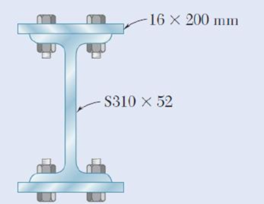
The American Standard rolled-steel beam shown has been reinforced by attaching to it two 16 × 200-mm plates, using 18-mm-diameter bolts spaced longitudinally every 120 mm. Knowing that the average allowable shearing stress in the bolts is 90 MPa, determine the largest permissible vertical shearing force.
The largest permissible vertical shearing force.
Answer to Problem 5P
The largest permissible vertical shearing force is
Explanation of Solution
Given information:
The diameter of bolt is
The longitudinal spacing is
The average shearing stress in the bolts is
Calculation:
Provide the section properties of the rolled steel beam
The area of the section is
The moment of inertia of the section
The Overall depth of the member
Calculate the moment of inertia as shown below.
Here, b is the breadth of the beam, h is the height of the beam, A is the area of the beam, and
For the top plate.
Calculate the area
Calculate the location of the centroid
Similarly calculate the moment of inertia for the bottom plate and rolled steel beam
| Part | Area, | Moment of Inertia, | ||
| Top plate | ||||
| Bottom plate |
Calculate the moment of inertia for the whole section as shown below.
Calculate the first moment of area
Substitute
Calculate the area of bolt as shown below.
Here,
Substitute
Calculate the force acting on the bolt
Here,
Substitute
Calculate the horizontal shear per unit length as shown below.
Substitute
Calculate the vertical shearing force (V) as shown below.
Substitute
Therefore, the largest permissible vertical shearing force is
Want to see more full solutions like this?
Chapter 6 Solutions
Mechanics of Materials, 7th Edition


- 2. Link AB, of width b 5 50 mm and thickness t 5 6 mm, is used to support the end of a horizontal beam. Knowing that the average normal stress in the link is 2140 MPa, and that the average shearing stress in each of the two pins is 80 MPa, determine (a) the diameter d of the pins, (b) the average bearing stress in the link.arrow_forwardAn elastomeric bearing (G=130 psi) is used to support a bridge girder as shown to provide flexibility during earthquakes. The beam must not displace more than 38 in. when a 5-kip lateral load is applied as shown. Knowing that the maximum allowable shearing stress is 60 psi, determine (a) the smallest allowable dimension b, (b) the smallest required thickness a.arrow_forward1. The member BD is attached to a rod at B, to a hydraulic cylinder at C, and to a fixed support at D. The bolt used at D acts in double shear and is made from a steel for which the maximum allowable shearing stress is Tallow = 40 ksi. The rod AB is made of a steel for which the maximum allowable tensile stress is Oallow = 60 ksi. The upward hydraulic force applied at C is 12 kip. 1) Calculate the minimum diameter of the rod AB. 2) Calculate the minimum diameter of the bolt at D. B FAB 12 kip 8 in. FBDarrow_forward
- Two wooden members of uniform rectangular cross section are joined by the simple glued scarf splice shown. Knowing that P =11 kN, determine the shearing stresses in the glued splice.arrow_forwardFour L102 x 102 x 9.5 steel angle shapes and a 12 x 400-mm steel plate are bolted together to form a beam with the cross section shown. The bolts are of 22-mm diameter and are spaced longitudinally every 120 mm. Knowing that the beam is subjected to a vertical shear of 240 kN, determine the average shearing stress in each bolt.arrow_forwardA 5/8-in.-diameter steel rod AB is fitted to a round hole near end C of the wooden member CD. For the loading shown, determine (a) the maximum average normal stress in the wood, (b) the distance b for which the average shearing stress is 100 psi on the surfaces indicated by the dashed lines, (c) the average bearing stress on the wood.arrow_forward
- Link AB, of width b = 2 in. and thickness t = 4 in., is used to support the end of a horizontal beam. Knowing that the average normal stress in the link is -20 ksi and that the average shearing stress in each of the two pins is 12 ksi determine (a) the diameter d of the pins, (b) the average bearing stress in the link. Barrow_forward4. The solid cylinders AB and BC are bonded together at B and are attached to fixed supports at A and C. Knowing that the modulus of rigidity is 3.7 x 10⁶ psi for aluminum and 5.6 x 10⁶ psi for brass, determine the maximum shearing stress (a) in cylinder AB, (b) in cylinder BC. Aluminum- 12 in. <-1.5 in. B T = 12.5 kip-in. Brass -2.0 in. C 18 in.arrow_forwardTwo wooden members of 80 × 120-mm uniform rectangular cross section are joined by the simple glued scarf splice shown. Knowing that β = 25° and that centric loads of magnitude P = 12 kN are applied to the members as shown, determine the in-plane shearing stress parallel to the splice and the normal stress perpendicular to the splice. (Round the final answers to one decimal place.)arrow_forward
- Two plates, eachin. thick, are used to splice a plastic strip as shown. Knowing that the ultimate shearing stress of the bonding between the surfaces is 130 psi, determine the factor of safety with respect to shear when P = 385 lb. in. in. 2-in. in. P The factor of safety with respect to shear isarrow_forwardIn the structure shown, an 8 mm diameter pin is used at A, and 12 mm diameter pins are used at B and D. Knowing that the allowable shearing stress is 120 MPa at all connections and that the allowable normal stress and bearing stress is 240 MPa in each of the two links joining B and D, determine the allowable load Parrow_forwardTwo wooden members are joined by plywood splice plates that are fully glued on the contact surfaces. Knowing that the clearance between the ends of the members is 6 mm and that the ultimate shearing stress in the glued joint is 2.5 MPa, determine the length L for which the factor of safety is 2.75 for the loading shown. Take P = 13 kN.arrow_forward
 Elements Of ElectromagneticsMechanical EngineeringISBN:9780190698614Author:Sadiku, Matthew N. O.Publisher:Oxford University Press
 Mechanics of Materials (10th Edition)Mechanical EngineeringISBN:9780134319650Author:Russell C. HibbelerPublisher:PEARSON
 Thermodynamics: An Engineering ApproachMechanical EngineeringISBN:9781259822674Author:Yunus A. Cengel Dr., Michael A. BolesPublisher:McGraw-Hill Education
 Control Systems EngineeringMechanical EngineeringISBN:9781118170519Author:Norman S. NisePublisher:WILEY
 Mechanics of Materials (MindTap Course List)Mechanical EngineeringISBN:9781337093347Author:Barry J. Goodno, James M. GerePublisher:Cengage Learning
 Engineering Mechanics: StaticsMechanical EngineeringISBN:9781118807330Author:James L. Meriam, L. G. Kraige, J. N. BoltonPublisher:WILEY