
Engineering Mechanics: Statics & Dynamics (14th Edition)
14th Edition
ISBN: 9780133915426
Author: Russell C. Hibbeler
Publisher: PEARSON
expand_more
expand_more
format_list_bulleted
Videos
Textbook Question
Chapter 6.6, Problem 95P
The nail cutter consists of the handle and the two cutting blades. Assuming the blades are pin connected at B and the surface at D is smooth, determine the normal force on the fingernail when a force of 1 lb is applied to the handles as shown. The pin AC slides through a smooth hole at A and is attached to the bottom member at C.
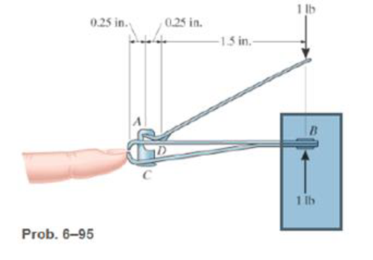
Prob. 6-95
Expert Solution & Answer
Want to see the full answer?
Check out a sample textbook solution
Students have asked these similar questions
6-127. Determine the clamping force exerted on the
smooth pipe at B if a force of 20 lb is applied to the handles
of the pliers. The pliers are pinned together at A.
20 lb
20 lb
10 in.
40°
1.5 in.
0.5 in.
B
R5-6. Determine the horizontal and vertical components
of force that the pins A and Cexert on the two-member frame.
500 N/m
-3m-
600 N/m
400 N/m
P4-1. Draw the free-body diagram of
object.
600 N m
-2 m-
3m
Chapter 6 Solutions
Engineering Mechanics: Statics & Dynamics (14th Edition)
Ch. 6.3 - In each case, calculate the support reactions and...Ch. 6.3 - Identify the zero-force members in each truss....Ch. 6.3 - Determine the force in each member of the truss....Ch. 6.3 - Determine the force in each member of the truss....Ch. 6.3 - Determine the force in each member of the truss....Ch. 6.3 - Determine the greatest load P that can be applied...Ch. 6.3 - Identify the zero-force members in the truss....Ch. 6.3 - Determine the force in each member of the truss....Ch. 6.3 - Determine the force in each member of the truss...Ch. 6.3 - Determine the force in each member of the truss...
Ch. 6.3 - Determine the force in each member of the truss....Ch. 6.3 - Determine the force in each member of the truss...Ch. 6.3 - Prob. 5PCh. 6.3 - Determine the force in each member of the truss,...Ch. 6.3 - Determine the force in each member of the truss...Ch. 6.3 - Determine the force in each member of the truss...Ch. 6.3 - Prob. 9PCh. 6.3 - Determine the force in each member of the truss...Ch. 6.3 - Determine the force in each member of the Pratt...Ch. 6.3 - Determine the force in each member of the truss...Ch. 6.3 - Determine the force in each member of the truss in...Ch. 6.3 - Members AB and BC can each support a maximum...Ch. 6.3 - Members AB and BC can each support a maximum...Ch. 6.3 - Determine the force in each member of the truss....Ch. 6.3 - If the maximum force that any member can support...Ch. 6.3 - Determine the force in each member of the truss...Ch. 6.3 - Determine the force in each member of the truss...Ch. 6.3 - Prob. 20PCh. 6.3 - Determine the force in each member of the truss...Ch. 6.3 - Determine the force in each member of the double...Ch. 6.3 - Prob. 23PCh. 6.3 - The maximum allowable tensile force in the members...Ch. 6.3 - Determine the force in each member of the truss in...Ch. 6.3 - The maximum allowable tensile force in the members...Ch. 6.4 - Determine the force in members BC, CF, and FE....Ch. 6.4 - Determine the force in members LK, KC, and CD of...Ch. 6.4 - Determine the force in members KJ, KD, and CD of...Ch. 6.4 - Determine the force in members EF, CF, and BC of...Ch. 6.4 - Determine the force in members GF, GD, and CD of...Ch. 6.4 - Determine the force in members DC, HI, and JI of...Ch. 6.4 - Determine the force in members DC, HC, and HI of...Ch. 6.4 - Determine the force in members ED, EH, and GH of...Ch. 6.4 - Determine the force in members HG, HE and DE of...Ch. 6.4 - Determine the force in members CD, HI, and CH of...Ch. 6.4 - Prob. 31PCh. 6.4 - Prob. 32PCh. 6.4 - Prob. 33PCh. 6.4 - Prob. 34PCh. 6.4 - Determine the force in members EF, CF, and BC, and...Ch. 6.4 - Determine the force in members AF, BF, and BC, and...Ch. 6.4 - Prob. 39PCh. 6.4 - Determine the force in members CD, CF, and CG and...Ch. 6.4 - Determine the force developed in members FE, EB,...Ch. 6.4 - Determine the force in members BC, HC, and HG....Ch. 6.4 - Determine the force in members CD, CJ, GJ, and CG...Ch. 6.4 - Determine the force in members BE, EF, and CB, and...Ch. 6.4 - Prob. 45PCh. 6.4 - Determine the force in members BC, CH, GH, and CG...Ch. 6.4 - Determine the force in members CD, CJ, and KJ and...Ch. 6.4 - Prob. 48PCh. 6.4 - Determine the force in members HI, FI, and EF of...Ch. 6.6 - In each case, identify any two-force members, and...Ch. 6.6 - Determine the force P needed to hold the 60-lb...Ch. 6.6 - Determine the horizontal and vertical components...Ch. 6.6 - If a 100-N force is applied to the handles of the...Ch. 6.6 - Determine the horizontal and vertical components...Ch. 6.6 - Determine the normal force that the 100-lb plate A...Ch. 6.6 - Determine the force P needed to lift the load....Ch. 6.6 - Prob. 19FPCh. 6.6 - Prob. 20FPCh. 6.6 - Determine the components of reaction at A and C....Ch. 6.6 - Determine the components of reaction at C. Prob....Ch. 6.6 - Determine the components of reaction at E. Prob....Ch. 6.6 - Determine the components of reaction at D and the...Ch. 6.6 - Determine the force P required to hold the 100-lb...Ch. 6.6 - In each case, determine the force P required to...Ch. 6.6 - Determine the force P required to hold the 50-kg...Ch. 6.6 - Determine the force P required to hold the 150-kg...Ch. 6.6 - Determine the horizontal and vertical components...Ch. 6.6 - Determine the horizontal and vertical components...Ch. 6.6 - Determine the force that the smooth rotor C exerts...Ch. 6.6 - The bridge frame consists of three segments which...Ch. 6.6 - Determine the reactions at supports A and B. Prob....Ch. 6.6 - Determine the horizontal and vertical components...Ch. 6.6 - Determine the reactions at the supports A, C, and...Ch. 6.6 - Determine the resultant force at pins A, B, and C...Ch. 6.6 - Determine the reactions at the supports at A, E,...Ch. 6.6 - The wall crane supports a load of 700 lb....Ch. 6.6 - The wall crane supports a load of 700 lb....Ch. 6.6 - Determine the horizontal and vertical components...Ch. 6.6 - The two-member structure is connected at C by a...Ch. 6.6 - The compound beam is pin supported at B and...Ch. 6.6 - When a force of 2 lb is applied to the handles of...Ch. 6.6 - The toggle clamp is subjected to a force F at the...Ch. 6.6 - The hoist supports the 125-kg engine. Determine...Ch. 6.6 - A 5-lb force is applied to the handles of the vise...Ch. 6.6 - Determine the force in members FD and DB of the...Ch. 6.6 - Determine the force that the smooth 20-kg cylinder...Ch. 6.6 - Prob. 85PCh. 6.6 - The pumping unit is used to recover oil. When the...Ch. 6.6 - Determine the force that the jaws J of the metal...Ch. 6.6 - Prob. 88PCh. 6.6 - Determine the horizontal and vertical components...Ch. 6.6 - The pipe cutter is clamped around the pipe P. If...Ch. 6.6 - Determine the force created in tire hydraulic...Ch. 6.6 - Determine the horizontal and vertical components...Ch. 6.6 - The constant moment of 50 N m is applied to the...Ch. 6.6 - Five coins are stacked in the smooth plastic...Ch. 6.6 - The nail cutter consists of the handle and the two...Ch. 6.6 - A man having a weight of 175 lb attempts to hold...Ch. 6.6 - Prob. 97PCh. 6.6 - The two member frame is pin connected at E. The...Ch. 6.6 - If the 300 kg drum has a center of mass at point...Ch. 6.6 - Operation of exhaust and intake valves in an...Ch. 6.6 - If a clamping force of 300 N is required at A,...Ch. 6.6 - If a force of F = 350 N is applied to the handle...Ch. 6.6 - Determine the horizontal and vertical components...Ch. 6.6 - The hydraulic crane is used to lift the 1400-lb...Ch. 6.6 - Determine force P on the cable if the spring is...Ch. 6.6 - Prob. 106PCh. 6.6 - If a force of F = 50 lb is applied to the pads at...Ch. 6.6 - The skid-steer loader has a mass of 1.18 Mg, and...Ch. 6.6 - Determine the force P on the cable if the spring...Ch. 6.6 - The spring has an unstretched length of 0.3 m....Ch. 6.6 - The spring has an unstretched length of 0.3 m....Ch. 6.6 - The piston C moves vertically between the two...Ch. 6.6 - Prob. 113PCh. 6.6 - The platform scale consists of a combination of...Ch. 6.6 - The three pin-connected members shown in the top...Ch. 6.6 - Determine the force in each member of the truss...Ch. 6.6 - Determine the force in each member of the truss...Ch. 6.6 - Determine the force in member GJ and GC of the...Ch. 6.6 - Determine the force in members GF, FB, and BC of...Ch. 6.6 - Determine the horizontal and vertical components...Ch. 6.6 - Determine the horizontal and vertical components...Ch. 6.6 - Determine the resultant forces at pins B and C on...
Knowledge Booster


Learn more about
Need a deep-dive on the concept behind this application? Look no further. Learn more about this topic, mechanical-engineering and related others by exploring similar questions and additional content below.Similar questions
- The 3600-lb car with rear wheel drive is attempting to push the 4500-lb crate. The center of gravity of the car is at G, and the coefficients of static friction are 0.6 at B and 0.2 at C. Determine if the crate will slide. (The car pulling the crate is analyzed in Prob. 7.19.)arrow_forward5-50. The machine shown is used for forming metal plates. It consists of two toggles ABC and DEF, which are operated by the hydraulic cylinder H. The toggles push the movable bar G forward, pressing the plate p into the cavity. If the force which the plate exerts on the head is P = 12 kN, determine the force F in the hydraulic cylinder when 0 = 30°. U D 200 mm 200 mm A 0 = 30° E -F F H B 0 = 30° F 200 mm 200 mm C Prob. 5-50 G р ▬▬▬ P = 12 kN ▬▬arrow_forwardP5-3. then draw the free-body diagrams of each member of the identify any two-force members, and frame. 800 N 200 N/m 6 m- -2 m m-arrow_forward
- 5-86. Operation of exhaust and intake valves in an automobile engine consists of the cam C, push rod DE, rocker arm EFG which is pinned at F, and a spring and valve, V. If the compression in the spring is 20 mm when the valve is open as shown, determine the normal force acting on the cam lobe at C. Assume the cam and bearings at H, I, and J are smooth. The spring has a stiffness of 300 N/m. 25 mm 40 mm E Prob. 5-86arrow_forwardP4-1. Draw the free-body diagram of object. 400 N/m -3 m -3m-arrow_forward6-89. Determine the horizontal and vertical components of force at each pin. The suspended cylinder has a weight of 80 lb. 4 ft 4 ft O E O A D O 3 ft- B 6 ft- Prob. 6-89 2 ft 1 ft of 3500 lb andarrow_forward
- P5-3. then draw the free-body diagrams of each member of the identify any two-force members, and frame. 400 N/m -3 m 1marrow_forward*5-36. A 300-kg counterweight, with center of mass at G, is mounted on the pitman crank AB of the oil-pumping unit. If a force of F - 5 KN is to be developed in the fixed cable attached to the end of the walking beam DEF, determine the torque M that must be supplied by the motor. -1.75 m -2.50 m 30 05 m 0.65 marrow_forwardP4-7. Determine the force P needed to cause impending motion of the block. 1m w = 100 N EIm . = 0.4arrow_forward
- 5-2. The coefficient of friction between the 200-15 homogeneous cylinder of Fig. PS-2 and horizontal plane is 0.4. The vertical plane is smooth. Deter- mine the frictional force exerted on the cylinder by the horizontal surface. 40-1barrow_forward6-50 The mass of the cylinder shown in Fig. 100 kg. Determine the reactions at contact points A and B. All surfaces are smooth. is 300 N 250 mm B 100 mmarrow_forward-27. The disk has a mass of 50 kg and the block has a nass of 12 kg. If the coefficients of friction at the points of contact are = 0.5 and = 0.2, respectively, deter- nine the smallest couple moment M which can be applied to he disk to cause motion. Neglect the mass of the connect- ng rod CD. 300 mm 30² Prob. 9-27arrow_forward
arrow_back_ios
SEE MORE QUESTIONS
arrow_forward_ios
Recommended textbooks for you
 International Edition---engineering Mechanics: St...Mechanical EngineeringISBN:9781305501607Author:Andrew Pytel And Jaan KiusalaasPublisher:CENGAGE L
International Edition---engineering Mechanics: St...
Mechanical Engineering
ISBN:9781305501607
Author:Andrew Pytel And Jaan Kiusalaas
Publisher:CENGAGE L
Mechanical SPRING DESIGN Strategy and Restrictions in Under 15 Minutes!; Author: Less Boring Lectures;https://www.youtube.com/watch?v=dsWQrzfQt3s;License: Standard Youtube License