
Concept explainers
Videos
Which elements (individual elements, not combinations of elements) of the networks in Fig. 7.64. are in series? Which are in parallel? As a check on your assumptions, be sure that the elements in series have the same current and that the elements in parallel have the same voltage. Restrict your decisions to single elements not combinations of elements.
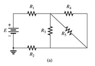
Fig 7.64
(a)
The elements of the network that are in series and in parallel.
Answer to Problem 1P
Explanation of Solution
Given:
A network is given as below.
Concept Used:
Elements in the series have the same current.
Elements in the parallels have the same voltage.
Calculation:
A network is given as below.

Since same current is flowing through
So,
Also, since same voltage is flowing through
So,
Conclusion:
Hence,
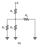
(b)
The elements of the network that are in series and in parallel.
Answer to Problem 1P
Explanation of Solution
Given:
A network is given as below.
Concept Used:
Elements in the series have the same current.
Elements in the parallels have the same voltage.
Calculation:
A network is given as below.

Since same current is flowing through
So,
And since same voltage is flowing through
So,
Conclusion:
Hence,
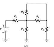
(c)
The elements of the network that are in series and in parallel.
Answer to Problem 1P
Explanation of Solution
Given:
A network is given as below.
Concept Used:
Elements in the series have the same current.
Elements in the parallels have the same voltage.
Calculation:
A network is given as below.

Since same current is flowing through
So,
Since same voltage is across
So,
Conclusion:
Hence,
Want to see more full solutions like this?
Chapter 7 Solutions
Introductory Circuit Analysis (13th Edition)
Additional Engineering Textbook Solutions
Fundamentals of Applied Electromagnetics (7th Edition)
Electrical Engineering: Principles & Applications (7th Edition)
Computer Systems: A Programmer's Perspective (3rd Edition)
Starting Out with Java: From Control Structures through Data Structures (3rd Edition)
Starting Out with Java: From Control Structures through Data Structures (4th Edition) (What's New in Computer Science)
C Programming Language


- Q 2) For the network in Fig. 7.64: a. Find the total resistance R, b. Find the source current I, and currents /, and Iy. c. Find current ls. d. Find voltages V; and Va. Ry R 120 40 R4 14 V V, R 120 Ryarrow_forwardFor the network of Fig. 7.86, Vp = 12 V. Determine: a. Ip. b. Vs and Vps- c. Vg and VGs- d. Vp. 18 V 2 k2 O Vp = 12 V + VG 12 VoMw VDS Ipss = 8 mA 680 k2 VGS Vs '110 k2 0.68 k2arrow_forward276 ||| SERIES-PARALLEL CIRCUITS *7. For the network in Fig. 7.67: a. Find currents I, I, and l b. Find voltages V, and V c. Find the power delivered to the 3 kfl resistor *& For the series-parallel configuration in Fig. 7.68 a. Find the source current , b. Find currents, and/ e. Find current l d. Find voltage V R₁1052 80 V = R₂ W 50 +20 V 50 592 w 4 R. 3802 ww 601 R₁4 R₁80 R, 212 + FIG. 7.68 Problem 8. FIG. 7.69 Problem 9. 9. Determine the currents /, and I, for the network in Fig. 7.69. 16 1 R₂ W www 250 12. For the network in Fig. 7.72: a. Determine the current 7. b. Calculate the currents I, and 1₂. e. Determine the voltage levels V, and V 8 20V M 8,30 [+ R₂30 R, GURGU FIG. 7.72 Problem 12. 48 V E = 28 V TOV R₂40 -79 R₂ *13. Determine the de levels for the transistor network in Fig. 7.73 using the fact that Vas-0.7 V, V-2V, and Ic - Ig That is a. Determine I, and lo -1k0 114 41242² FIG. 7.66 Problem 6 FIG. 7.67 Problem 7. R, 401 1₁ ly 4,340 R₂ 10. a. Find the magnitude and…arrow_forward
- 14. For the network of Fig. 7.86, Vp = 12 V. Determine: a. Ip. b. Vs and Vps- c. Vg and VGs. d. Vp.arrow_forwardFor the given circuit in Fig. 7, the voltage across the element is required to be measured using two voltmeters whose internal resistances are 300KW and 6MW. 1.a) Calculate the correct value. b) Calculate the values measured by each voltmeter and corresponding errorsarrow_forwardThe Permittivity of the Insulators increases when the Insulators suffers from cracks or breakages. Select one: O True Falsearrow_forward
- For the network of Fig. 7.91, VD 9 V. Determine:to. a. ID.b. VS and VDS.c. VG and VGS.d. VP.arrow_forwardSolve a) only.Draw the graph and show each steps clearlyarrow_forward16. Connect a lead between terminal B and the ground terminal of the power supply. This places terminal B at ground potential as shown Fig. 7-2. S1 0- 100mAdc mA R1 1K R2 35Vdc 1K R3 1.5K Fig. 7-2 17. Close switch S1 and measure the voltage at each terminal with respect to ground. Indicate voltage polarity. Connect the common lead of the VOM to ground (terminal B) and change the input polarity of the VOM when required. BAGL Terminal D = Terminal C =. Terminal A =, Vdc Vdc Vdc With respect to ground, terminal D is twenty volts positive, terminal C is ten volts positive, and terminal A is fifteen volts negative. Is terminal D more positive than terminal C? Is terminal B more positive than terminal A?- PRSITY SAINT SAPIE IFICATarrow_forward
- *21. For the network of Fig. 7.93, determine: a. Ipo and VGSo b. Vps and Vs. 18 V 2.2 k2 Ipss = 8 mA Vp = -8 V Vaso 0.39 k2 6-4 V FIG. 7.93 Problem 21.arrow_forward6. For the circuit board in Fig. 7.66: a. Find the total resistance R, of the configuration. b. Find the current drawn from the supply if the applied voltage is 48 V. c. Find the reading of the applied voltmeter. 10 6.8 kl 1.2 k 3.3 k 2 k RT 48 V 1 k 24 kf FIG. 7.66 Problem 6.arrow_forwardPlease write the detailed solution for every problem abovearrow_forward
 Introductory Circuit Analysis (13th Edition)Electrical EngineeringISBN:9780133923605Author:Robert L. BoylestadPublisher:PEARSON
 Delmar's Standard Textbook Of ElectricityElectrical EngineeringISBN:9781337900348Author:Stephen L. HermanPublisher:Cengage Learning
 Programmable Logic ControllersElectrical EngineeringISBN:9780073373843Author:Frank D. PetruzellaPublisher:McGraw-Hill Education
 Fundamentals of Electric CircuitsElectrical EngineeringISBN:9780078028229Author:Charles K Alexander, Matthew SadikuPublisher:McGraw-Hill Education
 Electric Circuits. (11th Edition)Electrical EngineeringISBN:9780134746968Author:James W. Nilsson, Susan RiedelPublisher:PEARSON
 Engineering ElectromagneticsElectrical EngineeringISBN:9780078028151Author:Hayt, William H. (william Hart), Jr, BUCK, John A.Publisher:Mcgraw-hill Education,