
Videos
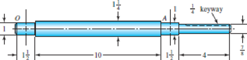
The figure shows a proposed design for the industrial roll shaft of Prob. 7–4. Hydrodynamic film bearings are to be used. All surfaces are machined except the journals, which are ground and polished. The material is 1035 HR steel. Perform a design assessment. Is the design satisfactory?
Problem 7–6
Bearing shoulder fillets 0.030 in, others
Weather the design is satisfactory or not.
Answer to Problem 6P
The design is satisfactory for crown gear.
Explanation of Solution
Write the expression for force acting on roller.
Here, normal force is
Write the expression for force acting on C along z axis.
Here, force on C in z axis is
Write the expression for torque.
Here, torque is
Write the expression for force at B along z axis.
Here, force at B along z axis is
Write the expression for force at B along y-axis
Here, force at B along y-axis is
Write the expression for moment about O.
Write the expression for moment about A.
Write the expression for moment at point C.
Write the expression for moment at A.
Write the expression for moment about O.
Write the expression for moment about A.
Write the expression for moment at point C along z-axis.
Write the expression for moment at A along z-axis.
Write the expression for total moment.
Here, bending moment in x-y plane is
Write the expression for total moment at D.
Here, moment on x-y plane at D is
Write the moment equation in x-y plane.
Integrate Equation (XVI).
Integrate Equation (XVII).
Apply boundary Equation, substitute
Substitute
Substitute
Substitute
Write the moment equation in x-z plane.
Integrate Equation (XVIII).
Integrate Equation (XIX).
Substitute
Substitute
Substitute
Substitute
Write the expression for flexural rigidity.
Here, flexural rigidity is
Write the expression for deflection at A.
Here, speed is
Write the expression for relative deflection.
Here, force is
Write the expression for deflection at B.
Write the expression for deflection at z.
Here, deflection at A is
Write the expression for relative deflection.
Here, force is
Write the expression for deflection at B.
Here, deflection at B is
Write the expression for gear mesh.
Here, gear mesh at B is
Write the expression for concentration factor for bending.
Here, concentration factor for bending is
Write the expression for concentration factor torsion.
Here, concentration factor for torsion is
Write the expression for endurance limit.
Here, endurance limit is
Write the expression for surface factor.
Here, surface factor is
Write the expression for size factor.
Here, size factor is
Write the expression for endurance limit at critical path.
Here, surface modification factor is
Conclusion:
The following figure shows roller forces.
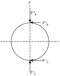
Figure-(1)
Substitute
Substitute
Substitute
Substitute
Substitute
The figure below shows the free body diagram and bending moment diagram.
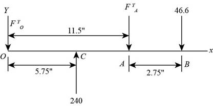
Figure-(2)
Substitute
Substitute
Substitute
The figure below shows the bending moment diagram for x-y plane.
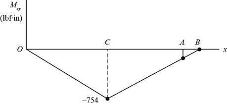
Figure-(3)
Substitute
The figure below shows free body diagram and the bending moment diagram in x-z plane.
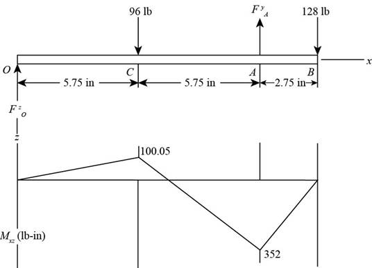
Figure-(4)
Substitute
Substitute
Substitute
Substitute
Substitute
Substitute
The figure below shows the bending moment diagram.
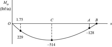
Figure-(5)
The figure below shows the forces in x-z plane.
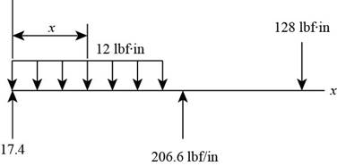
Figure-(6)
Substitute
The figure below shows the bending moment diagram.
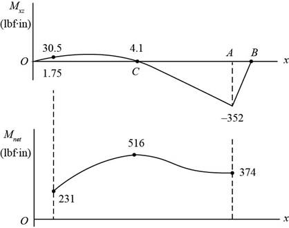
Figure-(7)
Substitute
Substitute
Calculate factor of safety.
The figure below shows forces in x-y plane.
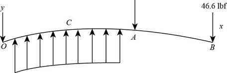
Figure-(8)
Substitute
Substitute
The figure below shows the forces on the system.
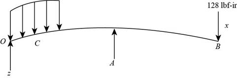
Figure-(9)
Substitute
Substitute
Substitute
Refer to table A-20, “Deterministic ASTM minimum tensile and yield strength for some hot rolled and cold drawn steels” to obtain tensile strength as
Substitute
Substitute
Substitute
Refer to table 7-1, “First iteration estimated for stress concentration factors” to obtain concentration factor for bending stress as
Refer to figure6-20, to obtain notch sensitivity as
Substitute
Substitute
Substitute
Refer to table 6-2, “Parameters for main surface condition factor” to obtain
Substitute
Substitute
Substitute
Substitute
The factor of safety is acceptable for crowned gear.
Thus, crowned gear is more reliable.
Want to see more full solutions like this?
Chapter 7 Solutions
Shigley's Mechanical Engineering Design (McGraw-Hill Series in Mechanical Engineering)


- Use the general shaft layout given and determine critical diameters of the shaft based on infinite fatigue life with a design factor of 1.5. Check for yielding. Check the slopes at the bearings for satisfaction of the recommended limits in Table 7-2. Assume that the deflections for the pulleys are not likely to be critical. 500 lbf 75 lbf 8-in dia. Bearing at O 500 lb d 10.0" 75 lb Material 1040 Q and T 18 in Use the following shaft layout assuming a pulley transmits torque through a key and keyseat at location A to another pulley at location B. Assume the tensions in the belt at pulley B are T₁ and T2, where T₁ is 15% of T2. NOTE: This is a multi-part question. Once an answer is submitted, you will be unable to return to this part. 10-in dia. 12 in T₂ T₁ The mean torque is 0 lb-in. The alternating torque is 2125 lb-in. The mean moment is 0 lb-in. The alternating moment is 5000 lb-in. 18.0" pulley diameter = 8.0" Sut 113 kpsi 10.0 B T2 T1 pulley diameter = 10.0" Sy 86 kpsi 12.0"…arrow_forwardUse the general shaft layout given and determine critical diameters of the shaft based on infinite fatigue life with a design factor of 1.5. Check for yielding. Check the slopes at the bearings for satisfaction of the recommended limits in Table 7-2. Assume that the deflections for the pulleys are not likely to be critical. 10 in 500 lbf 75 lbf 8-in dia. Bearing at O 10.0" 500 lb d 75 lb Material 1040 Q and T 18 in Use the following shaft layout assuming a pulley transmits torque through a key and keyseat at location A to another pulley at location B. Assume the tensions in the belt at pulley Bare T₁ and T2, where T₁ is 15% of T2. NOTE: This is a multi-part question. Once an answer is submitted, you will be unable to return to this part. 10-in dia. 12 in T₂ 8.0⁰ T₁ 18.0" 10.0" I B pulley diameter = 8.0" Sut 113 kpsi T2 T1 pulley diameter = 10.0" Sy 86 kpsi 12.0" Bearing at C Using the DE-Goodman criteria and a design factor of 1.5, calculate the diameter based on the shaft's loadings…arrow_forwardThe reducer input shaft shown in the figure is tapered It transmits moment with the help of a gear wheel. On the spindle, Fa = 552 N, Fr = 457 N, Ft = 1960 N from gear forces and belt mechanism incoming Fk = 2600 N radial force impact . The shaft rotates with n = 1090 rpm. Accept the shaft diameter in the A bearing as dA = 35 mm. Fixed ball suitable for Lh = 13500 h select bearing.arrow_forward
- The chain drive is mounted in the center for the system shown in figure.It can transmit 15 hp at a speed of 400 rpm and the sprocket has a pitch diameter of 6 inches. The shaft is made of ASTM-A 709 Grade 50 steel. A factor of safety of 2.5 is required. Is the design acceptable? Hint: You need to calculate torsion and bending stresses during solution.arrow_forwardThe reducer input shaft shown in the figure is taperedIt transmits moment with the help of a gear wheel.On the spindle, Fa = 552 N, Fr = 457 N, Ft = 1960 Nfrom gear forces and belt mechanismincoming Fk = 2600 N radial force impact. The shaft rotates with n = 1090 rpm.Accept the shaft diameter in the A bearing as dA = 35 mm.Fixed ball bearing for Lh = 13500 hselectarrow_forwardProblem 2: F = 10 kip -10 in- -5 in- -5 in- d/5 R. R1 d/ 10 R. 1.4 d- R2 I in The shaft shown above rotates at 1200 RPM and supports a 10 kip load. The material of the shaft is 1095 hot-rolled steel and its surface is machined and then polished. Using a factor of safety of 1.6, specify the minimum value of diameter d for a life of 1,000 hours.arrow_forward
- A gear drive consists of a 16-tooth 20° steel spur pinion and a 48-tooth cast-iron gear having a pitch of 12 teeth/in. For a power input of 1.35 hp at a pinion speed of 700 rev/min, select a face width based on an allowable contact stress of 100 kpsi. Refer to table number 14-8 for elastic coefficient. The face width based on an allowable contact stress of 100 kpsi is in.arrow_forwardA stepped shaft has dimensions of D = 2 in., d = 1 in., and r= 0.1 in. It is machined from AISI steel of 200 Bhn hardness. The load is fully reversed axial torsion. 30 seconds of time history of the nominal torsional stress in the 1 in, section of the shaft, Tnom(t) = Tr/J, is shown (dots indicate the beginning/end of each load cycle; there are 20 cycles total in 30 seconds.). This duty cycle continues repeating. (a) Use Miner's rule to estimate the life of the shaft in cycles. (b) What is the expected life in hours. Su 0.5HB for steel. 30 20 10 -10 -20 -30 30 seconds D=2 in. d=1 in. f= 0.1 in. 200 Bhnarrow_forwardThe rotating shaft shown in the figure is machined from AISI 1040 CD steel (sy = 490 MPa, Sut = 590 MPa). It is subjected to a transverse force of F = 8 kN between the supports. The system designed to be operated at a temperature of 120°C with a reliability of 99%. Estimate the number of cycles to failure. All dimensions are in mm. Assume all fillets are 3mm in radius. 25 D. 20 20 -35 D. 180- 3 R. 500 F 280 -175- -50 D. 25 D. | ª -20 20arrow_forward
- A gear reduction unit uses the countershaft shown in the figure. Gear A receives power from another gear with the transmitted force FA applied at the 20° pressure angle as shown. The power is transmitted through the shaft and delivered through gear B through a transmitted force Fg at the pressure angle shown. For the steel countershaft shown below, assume the bearings have a maximum slope specification of 0.062° for good bearing life. Check wether the shaft dia below meets the requirement. If not determine a suitable shaft diameter. 400 mm FB 350 mm 25° 300 mm FA = 11 kN• 20° 50-mm dia. Gear A, 600-mm dia. Gear B, 300-mm dia. mm. The minimum shaft diameter is determined to bearrow_forward2- A chain drive using bush roller chain transmits 5500 W of power. The driving shaft on an electric motor runs at 1440 r.p.m. and velocity ratio is 4.6:1. The drive is required to operate continuously with periodic lubrication and driven machine is such that load can be regarded as fairly constant. Considering the center distance to be as minimum as possible, design the chain drive by calculating leading dimensions, number of teeth and length of the chain.arrow_forwardBearings Motor Spur gears Worm Bronze bushings - 2L 's C.I. Collar ´bearing 2 [ 's The press shown in the following figure has a rated load of 5000 Ibf. The twin screws have Acme threads, a diameter of 3 in, and a pitch of 1/2 in. Coefficients of friction are 0.05 for the threads and 0.06 for the collar bearings. Collar diameters are 5 in. The gears have an efficiency of 95 percent and a speed ratio of 75:1. A slip clutch, on the motor shaft, prevents overloading. The full-load motor speed is 1720 rev/min. (a) When the motor is turned on, how fast will the press head move? (b) What should be the horsepower rating of the motor?arrow_forward
 Elements Of ElectromagneticsMechanical EngineeringISBN:9780190698614Author:Sadiku, Matthew N. O.Publisher:Oxford University Press
 Mechanics of Materials (10th Edition)Mechanical EngineeringISBN:9780134319650Author:Russell C. HibbelerPublisher:PEARSON
 Thermodynamics: An Engineering ApproachMechanical EngineeringISBN:9781259822674Author:Yunus A. Cengel Dr., Michael A. BolesPublisher:McGraw-Hill Education
 Control Systems EngineeringMechanical EngineeringISBN:9781118170519Author:Norman S. NisePublisher:WILEY
 Mechanics of Materials (MindTap Course List)Mechanical EngineeringISBN:9781337093347Author:Barry J. Goodno, James M. GerePublisher:Cengage Learning
 Engineering Mechanics: StaticsMechanical EngineeringISBN:9781118807330Author:James L. Meriam, L. G. Kraige, J. N. BoltonPublisher:WILEY