
Concept explainers
Videos
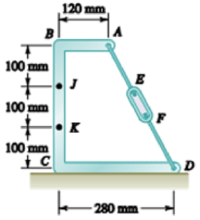
Knowing that the turnbuckle has been tightened until the tension in wire AD is 850 N, determine the internal forces at the point indicated: 7.154 Point J.
The internal forces.
Answer to Problem 7.154RP
The internal forces are
Explanation of Solution
The free body diagram is given in figure 1.
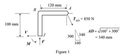
From the diagram, net force along horizontal and vertical directions is zero. Write the equilibrium condition for the forces.
Here,
The net moment at point J is zero. Therefore, the equilibrium condition is,
Here, M is the moment of internal force.
Conclusion:
Substitute 280 mm for CD, 120 mm for AB, 300 mm for BC and 850 N for
Substitute 280 mm for CD, 120 mm for AB, 300 mm for BC and 850 N for
Substitute 400 N for V, 750 N for F, 100 mm for BJ and 120 mm for AB in the expression for M.
Therefore, the internal forces are
Want to see more full solutions like this?
Chapter 7 Solutions
Vector Mechanics for Engineers: Statics and Dynamics


- For the cable shown, determine the tension in segment AB.. 7.3 KN 6.8 KN 5.2 KN 6.9 KNarrow_forwardThe pipe ABCDE is supported by ball-and-socket joints at A and D and by cable ECF that passes through a ring C with negligible friction and is attached to hooks at E and F. Knowing that the frame supports a uniformly distributed load of 1500 N/m along segment AB, do the following.1) Shows the correct vector representation of the resultant of the two tension forces acting at ring C. Note that T_CF = T_CE = T2) Explain along which line/axis you can sum moments to generate an equilibrium equation with only the magnitude of the tension force as the unknown. Explain your choice.3) Find the magnitude of the tension force.arrow_forwardDetermine the value of w and P such that the resultant of the system is a downward force of magnitude 1200 N acting 3.6 m to the right of A. Determine the magnitude of the uniform load w. a.252 N/m b.646.1 N/m c.387.7 N/m d.553.8 N/marrow_forward
- 2. To satisfy design limitations it is necessary to determine the effect of the 2-kN tension in the cable on the shear, tension, and bending of the fixed I-beam. For this purpose, replace this force by its equivalent of two forces at A, F; parallel and Fn perpendicular to the beam. Determine F; and Fn. 20° 2 kN 30°arrow_forwardA 175-kg utility pole is used to support at C the end of an electric wire. The tension in the wire is 600 N, and the wire forms an angle of 15° with the horizontal at C . Determine the largest and smallest allowable tensions in the guy cable BD if the magnitude of the couple at A may not exceed 500 N·m.arrow_forwardQ.5) The bent bar as shown below is supported by a cable AE, a ball-and-socket joint at O, and a journal (slider) bearing at D. At the journal bearing D, the momen support reactions and the force support reaction along y-axis are zero. The 2-kip force and the 6 kip-ft couple-moment are parallel to z-axis and applied at point B. Determine the tension in the cable AE and the support reactions at O and D. X A / 0 4 ft Z 16 kip-ft 2 ft B 2 ft 2 kips BANES 3 ft [ 1 kip = 1000 lb. ] E 14 ft yarrow_forward
- Cables OA, OB, OC, and the vertical cable, knotted at O, support the 108lb weight. Cables OA and OB lie in the x-y plane. Determine the tension in Cable OC.a. 468lb b. 351lbc. 45.0lb d. 117lb Determine the tension in Cable OB.a. 45.0lb b. 27.0lbc. 33.8lb d. 21.6lb Determine the tension in Cable OA.a. 28.8lb b. 36.0lbc. 56.2lb d. 15.2lbarrow_forwardTwo steel pipes AB and BC, each having a mass per unit length of 28 kg/m, are welded together at B and supported by three wires. Knowing that a = 0.4 m, determine the tension in each wire. (Round the final answers to two decimal places.)arrow_forwardThe uniform 18kg Bar OA is held in the position shown by a smooth pin at O, and the cable AB which is in tension as shown. 1.5 m 60° -1.2 m The magnitude of the tension in the cable AB is (Answer in Newtons) Answer: Next paarrow_forward
- STATICS 1. Three bars, hinged at A and D and pinned at B and C as shown, form a four-link mechanism. Determine the value of P that will prevent motion. ( 60° В 45° 45 60" P 20 kN A. 2. Solve for resultant and compute the values of P and F. Assuming each side is 1' A B D 361 Ib 3. Determine the reactions at A, B, C, and D W = 200 kN W = 400 kN 1m 2 m 5.6 marrow_forwardFor the frame and loading shown, determine the internal forces at the point indicated:Point Jarrow_forwardPulleys A and B are mounted on bracket CDEF. The tension on each side of the two belts is given as TÃ1 = 126 lb, TẠ2 = 160 lb, TB₁ = 210 lb, and TB2 = 150 lb. Replace the four forces with a single equivalent force, and determine where its line of action intersects the bottom edge of the bracket. 2 in. 1 in. C F r = 2 in. r= 1in. -6 in- TA1 lb A -6 in.- TA2 lb B D E 4 in. The resultant force R is 352.66 lb x 22.3 The point d where the resultant force intersects the line EF is $25° TB1 lb 125° 2.8 TB2 lb in.arrow_forward
 Elements Of ElectromagneticsMechanical EngineeringISBN:9780190698614Author:Sadiku, Matthew N. O.Publisher:Oxford University Press
 Mechanics of Materials (10th Edition)Mechanical EngineeringISBN:9780134319650Author:Russell C. HibbelerPublisher:PEARSON
 Thermodynamics: An Engineering ApproachMechanical EngineeringISBN:9781259822674Author:Yunus A. Cengel Dr., Michael A. BolesPublisher:McGraw-Hill Education
 Control Systems EngineeringMechanical EngineeringISBN:9781118170519Author:Norman S. NisePublisher:WILEY
 Mechanics of Materials (MindTap Course List)Mechanical EngineeringISBN:9781337093347Author:Barry J. Goodno, James M. GerePublisher:Cengage Learning
 Engineering Mechanics: StaticsMechanical EngineeringISBN:9781118807330Author:James L. Meriam, L. G. Kraige, J. N. BoltonPublisher:WILEY