
Loose Leaf for Engineering Circuit Analysis Format: Loose-leaf
9th Edition
ISBN: 9781259989452
Author: Hayt
Publisher: Mcgraw Hill Publishers
expand_more
expand_more
format_list_bulleted
Concept explainers
Videos
Textbook Question
Chapter 7.5, Problem 10P
Derive an expression for vout in terms of vs for the circuit shown in Fig. 7.29.
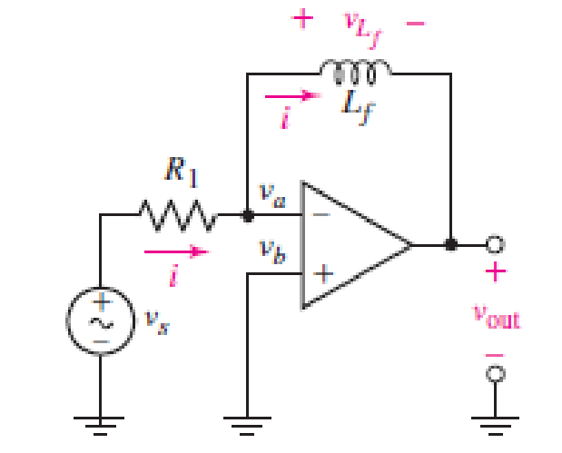
FIGURE 7.29
Expert Solution & Answer
Want to see the full answer?
Check out a sample textbook solution
Students have asked these similar questions
Making the assumption that the circuits in Fig. 7.50 have been connected for a
very long time, determine the value for each current labeled ix.
Rp
->
sa
Figure 7.52 Bia
resistance, RG
Determine ΔE if two semiconductor gages (Sg = 100) are employed in the double- potentiometer circuit shown under case 3 of Fig. 7.15.
Both active gages have R1 = R2 = Rg = 500Ω. Assume Ig = 100mA, ε = +1000µ on R1 and -1000µ on R2
Chapter 7 Solutions
Loose Leaf for Engineering Circuit Analysis Format: Loose-leaf
Ch. 7.1 - Determine the current flowing through a 5 mF...Ch. 7.1 - Prob. 2PCh. 7.1 - Prob. 3PCh. 7.2 - 7.4 The current through a 200 mH inductor is shown...Ch. 7.2 - The current waveform of Fig. 7.14a has equal rise...Ch. 7.2 - Prob. 6PCh. 7.2 - Let L = 25 mH for the inductor of Fig. 7.10. (a)...Ch. 7.3 - Find Ceq for the network of Fig. 7.23. FIGURE...Ch. 7.4 - If vC(t) = 4 cos 105t V in the circuit in Fig....Ch. 7.5 - Derive an expression for vout in terms of vs for...
Ch. 7.6 - Prob. 11PCh. 7 - Making use of the passive sign convention,...Ch. 7 - Prob. 2ECh. 7 - (a) If the voltage waveform depicted in Fig. 7.42...Ch. 7 - A capacitor is constructed from two brass plates,...Ch. 7 - Prob. 5ECh. 7 - Prob. 6ECh. 7 - Design a capacitor whose capacitance can be varied...Ch. 7 - Design a capacitor whose capacitance can be varied...Ch. 7 - Prob. 9ECh. 7 - Assuming the passive sign convention, sketch the...Ch. 7 - Prob. 11ECh. 7 - Prob. 12ECh. 7 - Prob. 13ECh. 7 - Calculate the power dissipated in the 40 resistor...Ch. 7 - Prob. 15ECh. 7 - Design a 30 nH inductor using 28 AWG solid soft...Ch. 7 - Prob. 17ECh. 7 - Prob. 18ECh. 7 - Prob. 19ECh. 7 - Prob. 20ECh. 7 - Calculate vL and iL for each of the circuits...Ch. 7 - The current waveform shown in Fig. 7.14 has a rise...Ch. 7 - Determine the inductor voltage which results from...Ch. 7 - Prob. 24ECh. 7 - The voltage across a 2 H inductor is given by vL =...Ch. 7 - Calculate the energy stored in a 1 nH inductor if...Ch. 7 - Determine the amount of energy stored in a 33 mH...Ch. 7 - Making the assumption that the circuits in Fig....Ch. 7 - Calculate the voltage labeled vx in Fig. 7.52,...Ch. 7 - Prob. 30ECh. 7 - Prob. 31ECh. 7 - Determine an equivalent inductance for the network...Ch. 7 - Using as many 1 nH inductors as you like, design...Ch. 7 - Compute the equivalent capacitance Ceq as labeled...Ch. 7 - Prob. 35ECh. 7 - Prob. 36ECh. 7 - Reduce the circuit depicted in Fig. 7.59 to as few...Ch. 7 - Refer to the network shown in Fig. 7.60 and find...Ch. 7 - Prob. 39ECh. 7 - Prob. 40ECh. 7 - Prob. 41ECh. 7 - Prob. 42ECh. 7 - Prob. 43ECh. 7 - Prob. 44ECh. 7 - Prob. 45ECh. 7 - Prob. 46ECh. 7 - Prob. 47ECh. 7 - Let vs = 100e80t V with no initial energy stored...Ch. 7 - Prob. 49ECh. 7 - Prob. 50ECh. 7 - Interchange the location of R1 and Cf in the...Ch. 7 - For the integrating amplifier circuit of Fig....Ch. 7 - Prob. 53ECh. 7 - For the circuit shown in Fig. 7.73, assume no...Ch. 7 - A new piece of equipment designed to make crystals...Ch. 7 - An altitude sensor on a weather balloon provides a...Ch. 7 - One problem satellites face is exposure to...Ch. 7 - The output of a velocity sensor attached to a...Ch. 7 - A floating sensor in a certain fuel tank is...Ch. 7 - (a) If Is = 3 sin t A, draw the exact dual of the...Ch. 7 - Draw the exact dual of the simple circuit shown in...Ch. 7 - (a) Draw the exact dual of the simple circuit...Ch. 7 - (a) Draw the exact dual of the simple circuit...Ch. 7 - Prob. 64ECh. 7 - Prob. 65ECh. 7 - Prob. 66ECh. 7 - Prob. 67ECh. 7 - Prob. 68ECh. 7 - Prob. 69ECh. 7 - Prob. 70ECh. 7 - For the circuit of Fig. 7.28, (a) sketch vout over...Ch. 7 - (a) Sketch the output function vout of the...Ch. 7 - For the circuit of Fig. 7.72, (a) sketch vout over...
Knowledge Booster


Learn more about
Need a deep-dive on the concept behind this application? Look no further. Learn more about this topic, electrical-engineering and related others by exploring similar questions and additional content below.Similar questions
- Practice Problem 7.5 Determine i, i.. and v, for all i in the circuit shown in Fig. 7.22. Assume that the switch was closed for a long time. It should be noted that opening a switch in series with an ideal current source creates an infinite voltage at the current source terminals. Clearly this is impossi- blc. For the purposes of problem solving, we can place a shunt resis- tor in parallel with the source (which now makes it a voltage source in series with a resistor). In more practical circuits, devices that act like curent sources are, for the most part, electronic circuits. These circuits 18 A will allow the source to act like an ideal current source over its oper- ating range but voltage-limit it when the load resistor becomes too large (as in an open circuit). 3 2 www 1=0 IH Figure 7.22 For Practice Proh 75.arrow_forwardQi Find Fcwl for the fullowing fuaction using differentiation property 7. 12arrow_forwardIn the following problems, unless otherwise stated, assume 4,Cor H„Cor = 100 µA/V², a = 0, and VTh = 0.4 V for NMOS devices and -0.4 V for PMOS devices. 200 µA/V². 1. In the circuit of Fig. 7.39, determine the maximum allowable value of W/L if M1 must VoD = 1.8 V 50 k2 1 k2 M1 Figure 7.39 remain in saturation. Assume A = 0.arrow_forward
- EXAMPLE 7.16 The levels of Vps and Ip are specified as Vps = Vnn and Ip = Ipon) for the network of Fig. 7.54. Determine the levels of Vpp and Rp- Rp 10 MQ VasioN 6 V Ipe=4 mA Vas =3V FIG. 7.54arrow_forward20. For the self-bias configuration of Fig. 7.92, determine: a. Ipo and VGSg b. Vps and Vp. 14 V 1.2 k2 Ipss = 6 mA Vp =-4 V Vaso 1 MQ 0.43 kQ FIG. 7.92 Problem 20.arrow_forward2.15 Design Problem for DC Circuits EXAMPLE 7.16 The levels of Vps and Ip are specified as Vps = VDD and Ip = ID(on) for the network of Fig. 7.54. Determine the levels of Vpp and Rp. VDD 10 ΜΩ RD VGS(on) = 6 V ID(on) = 4 mA VGS(Th) = 3 V FIG. 7.54 Figure 2.14 Example for Design Problemarrow_forward
- 2.12 Example for E-MOSFET Voltage Divider Bias Circuit EXAMPLE 7.11 Determine ID, VGS, and Vps for the network of Fig. 7.44. 22 ΜΩ 18 ΜΩ 9 40 V G ENGG CC ORT N Voso FIG. 7.44 D 3kQ OS 100 x Vps 2N4351 VGS (Th) = 5 V ID (on) = 3 mA at VGS (on) = 10 V 0.82 kQ2 Figure 2.12 Example for E-MOSFET Voltage Divider Bias Circuit.arrow_forwardThe switch in the circuit seen in fig 7.54arrow_forwardQuestion 7.30 The p-channel FETsFor the network of Fig. 7.104, determine:a. IDQ and VGSQ.b. VDS.c. VD.arrow_forward
arrow_back_ios
SEE MORE QUESTIONS
arrow_forward_ios
Recommended textbooks for you
 Introductory Circuit Analysis (13th Edition)Electrical EngineeringISBN:9780133923605Author:Robert L. BoylestadPublisher:PEARSON
 Delmar's Standard Textbook Of ElectricityElectrical EngineeringISBN:9781337900348Author:Stephen L. HermanPublisher:Cengage Learning
 Programmable Logic ControllersElectrical EngineeringISBN:9780073373843Author:Frank D. PetruzellaPublisher:McGraw-Hill Education
 Fundamentals of Electric CircuitsElectrical EngineeringISBN:9780078028229Author:Charles K Alexander, Matthew SadikuPublisher:McGraw-Hill Education
 Electric Circuits. (11th Edition)Electrical EngineeringISBN:9780134746968Author:James W. Nilsson, Susan RiedelPublisher:PEARSON
 Engineering ElectromagneticsElectrical EngineeringISBN:9780078028151Author:Hayt, William H. (william Hart), Jr, BUCK, John A.Publisher:Mcgraw-hill Education,
Introductory Circuit Analysis (13th Edition)
Electrical Engineering
ISBN:9780133923605
Author:Robert L. Boylestad
Publisher:PEARSON
Delmar's Standard Textbook Of Electricity
Electrical Engineering
ISBN:9781337900348
Author:Stephen L. Herman
Publisher:Cengage Learning
Programmable Logic Controllers
Electrical Engineering
ISBN:9780073373843
Author:Frank D. Petruzella
Publisher:McGraw-Hill Education
Fundamentals of Electric Circuits
Electrical Engineering
ISBN:9780078028229
Author:Charles K Alexander, Matthew Sadiku
Publisher:McGraw-Hill Education
Electric Circuits. (11th Edition)
Electrical Engineering
ISBN:9780134746968
Author:James W. Nilsson, Susan Riedel
Publisher:PEARSON
Engineering Electromagnetics
Electrical Engineering
ISBN:9780078028151
Author:Hayt, William H. (william Hart), Jr, BUCK, John A.
Publisher:Mcgraw-hill Education,
ENA 9.2(1)(En)(Alex) Sinusoids & Phasors - Explanation with Example 9.1 ,9.2 & PP 9.2; Author: Electrical Engineering Academy;https://www.youtube.com/watch?v=vX_LLNl-ZpU;License: Standard YouTube License, CC-BY
Electrical Engineering: Ch 10 Alternating Voltages & Phasors (8 of 82) What is a Phasor?; Author: Michel van Biezen;https://www.youtube.com/watch?v=2I1tF3ixNg0;License: Standard Youtube License