
Concept explainers
Videos
The equation for unknown flow rates or diameters for each pipe section in the pipe networks and branching pipes.
The analogy between the electric current in electric circuits and fluid flow in pipe networks.
Answer to Problem 186P
The total discharge in the branched pipe is
The analogy of network pipe is
Explanation of Solution
The following figure represents the branched pipes.
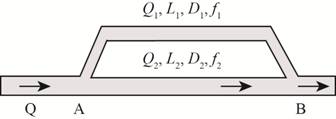
Figure-(1)
Write the expression for the area of pipe.
Here, the diameter of pipe is
Write the expression for the discharge rate in the pipe.
Here, the discharge in the pipe is
Write the expression for head loss in the pipe.
Here, the loss head is
Write the expression for total discharge in branched pipes.
Here, the total discharge in pipe is
Write the expression for head loss in the pipe 1.
Here, the velocity in pipe 1 is
Write the expression for head loss in the pipe 2.
Here, the velocity in pipe 2 is
The following figure represents the T-pipe network.

Figure (2)
Write the expressions for head loss in pipe 1.
Write the expressions for head loss in pipe 2.
Write the expressions for head loss in pipe 3.
Here, the discharge in pipe 3 is
Write the expression for loop method.
Here, the analogy of network pipe is
Calculation:
Substitute
Here, the area of pipe 1 is
Substitute
Here, the area of pipe 2 is
Substitute
Substitute
Substitute
Substitute
Substitute
The total discharge in the branched pipe is
Substitute
The analogy of network pipe is
Conclusion:
The analogy of network pipe is
The total discharge in the branched pipe is
Want to see more full solutions like this?
Chapter 8 Solutions
Fluid Mechanics: Fundamentals and Applications


- The losses per unit length pipe^h/l in turbulent flow through small pipe depend upon Velocity, Diameter, Gravity, Dynamic viscosity and Density. Determine the general from of equation.arrow_forwardDiscussion 1- Indicate the factors affecting the Reynotes number (Re). 2. The limits are gaved to the Reynolds number (Re) that if they less than 2000 it is the laminar flow and if they more than 4000 The flow is turbubent but there is a possibility to change those limits. 3-Discuss the importance of the infinite medium. Worksheet No. Risc of W.L. in Time for Risc in Collecting Tank (cm) W.L. (sec.) 1 s 45 2 s 26.5 3 s 21.5 4 % 12.75 s s 7 6 s s Diameter of pipe = 1.8 cm Length of pipe = 87 cm Area of Collecting Tank = 13 x 8.5 cm® @ Temperature of water = 30arrow_forwardTwo pipes of different diameters are joined together in series. The smaller pipe has a diameter of 0.1m and length of 14m and the larger pipe a diameter of 0.2m and length of 14m. Oil (density 800kg/m3, viscosity 0.2kg/ms flows through the pipes with a volume flow rate of 0.02m /s. Calculate the pressure drop over the pipes to the nearest 100Pa.arrow_forward
- (b) Fluid flow through a horizontal circular pipe of inner radius of 2 cm with centerline velocity as shown in Table 1. Based on Table 1 and setting given to you; (i) Determine the average velocity, maximum velocity and volume flowrate; and (ii) Calculate and draw the velocity profile for the given flow. Table 1: Setting of Question Centerline Velocity (m/s) Density (kg/m³) Dynamic Viscosity (Pa.s) 1.0 1.225 1.802 x 10⁻⁵arrow_forwardA small capillary with an inside diameter of 2.22 x 10⁻³m and a length 0.317m is being used to continuously measure the flow rate of a liquid having a density of 875 kg/m3 and viscosity of 1.13 x 10³ Pa-s. The pressure drop reading across the capillary during flow is 0.0655m water (Density is 996 kg/m3). What is the flowrate in cu.fps?arrow_forwardWater at 303k s flowing at the rate -4 6.3 X10 m²/s of an inside diameter (16) in a pipe having án inside diameter Cib) 52-5mm.' e Reynolds number. Calculate the Given Density of water at 303k water is 0.8cp is 996 kq lm3. Im? Viscosity ofarrow_forward
- A pitot-static probe is used to determine the flow velocity by measuring the differential pressure as shown in Figure 7. The pressure difference sensor used in the system is electronic types and the output of the device is measured in voltage. The output of the pressure device is 3.5 V and the linear relationship between the device and the pressure difference is 10 kPa/v. i. Derive pitot formula to obtain flow velocity from Bernoulli equation, ii. Calculate the pressure difference inside the system, iii. Determine the velocity inside the system if the the fluid is water, and iv. Explain the cause that / ontirbute to inaccurary in the velocity reading. Fluid Flow, V Stagnation Static pressure pressure Pi-P2 Figure 7: Pitot static probearrow_forwardA piping system consists of three pipes arranged in series, the lengths of the pipes are 1200 m, 750 m and 600 m and diameters are 750 mm, 600 mm, 450 mm respectively. Transform the system to an equivalent 450 mm diameter pipearrow_forwardDraw a diagram to explain what it means: flow separation, the mechanism by which fluid separation occurs, and give examples of how to delay separation and its effect on resistancearrow_forward
- Consider an oil flow of 12 m³/h in a long, straight and smooth pipe with diameter of 7 cm. What is the pressure loss per meter? Oil absol viscosity is 0,1 kg/ms and density is 900 kg/m³. Friction factor for laminar flow can be calculated from 64 f=t Round off the answer to an integer in Pa/m, but enter the answer without the unit. 0.1 0.09 0.08 0.07 0.06- 0.05 0.04- 0.03 0.025- 0.00 Lamitin THW 1 Transition ang Wholly turbulent flow Suth 0.05 0.04 0.03 0.02 0.015 0.01 0.008 0.006 0.004 0.002 0.001 0.0008 0,0004 0.0002 00001 300006 000001 Darrow_forwardWhat is the Reynolds number for a straight and perfectly smooth pipe of length 500 m and diameter 0.2 m, transporting oil (density 900 kg/m3 and viscosity 0.5 Pa-s) at a flow rate of 100 kg/s from sea level to an elevated height 10 m above sea level? What is the viscous pressure drop along the pipe?arrow_forwardMechanical-Energy Balance and Friction Losses. Hot water is being discharged from a storage tank at the rate of 0.223 ft3/s. The process flow diagram and conditions are the same as given in Example 2.10-6, except for different nominal pipe sizes of schedule 40 steel pipe as follows. The 20-ft-long outlet pipe from the storage tank is 1 1/2 in. pipe instead of 4-in. pipe. The other piping, which was 2-in. pipe, is now 2.5-in. pipe. Note that now a sudden expansion occurs after the elbow in the 1 1/2 in. pipe to a 2 1/2 in. pipe.arrow_forward
 Elements Of ElectromagneticsMechanical EngineeringISBN:9780190698614Author:Sadiku, Matthew N. O.Publisher:Oxford University Press
 Mechanics of Materials (10th Edition)Mechanical EngineeringISBN:9780134319650Author:Russell C. HibbelerPublisher:PEARSON
 Thermodynamics: An Engineering ApproachMechanical EngineeringISBN:9781259822674Author:Yunus A. Cengel Dr., Michael A. BolesPublisher:McGraw-Hill Education
 Control Systems EngineeringMechanical EngineeringISBN:9781118170519Author:Norman S. NisePublisher:WILEY
 Mechanics of Materials (MindTap Course List)Mechanical EngineeringISBN:9781337093347Author:Barry J. Goodno, James M. GerePublisher:Cengage Learning
 Engineering Mechanics: StaticsMechanical EngineeringISBN:9781118807330Author:James L. Meriam, L. G. Kraige, J. N. BoltonPublisher:WILEY