
Videos
An industrial load is modeled as a series combination of an inductor and a resistance as shown in Fig. 9.89. Calculate the value of a capacitor C across the series combination so that the net impedance is resistive at a frequency of 2 kHz.
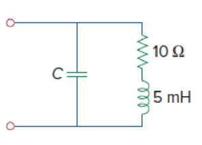
Figure 9.89
Find the value of capacitor
Answer to Problem 89CP
When the net impedance is resistive at a frequency of
Explanation of Solution
Given data:
Refer to Figure 9.89 in the textbook.
The value of frequency
Formula used:
Write a general expression to calculate the impedance of a resistor.
Here,
Write a general expression to calculate the impedance of an inductor.
Here,
Write a general expression to calculate the impedance of a capacitor.
Here,
Write a general formula to calculate the angular frequency.
Here,
Calculation:
Refer to the given circuit, the value of resistor
In the given circuit, the series of combination of resistor and inductor is connected in parallel with the capacitor.
The equivalent impedance of the given circuit is written as follows using equations (1), (2) and (3).
Simplify the above equation as follows:
Simplify the above equation as follows:
The equivalent impedance must be resistive when
Equate the imaginary part of above equation to zero.
Simplify the above equation as follows:
Simplify the above equation to find
Substitute
Substitute
Simplify the above equation as follows:
Conclusion:
Thus, when the net impedance is resistive at a frequency of
Want to see more full solutions like this?
Chapter 9 Solutions
Fundamentals of Electric Circuits


- A capacitor is connected in parallel with a load of S= 6000 VA, and pf-0.8 lag. The load is operating at 180 V and a frequency of 60 Hz. Calculate the capacitance value that will correct the power factor to pf%3D1. Select one: O a. None of them O b.0.47 mf O c.0.295 mf O d. 0.354 mfarrow_forwardIn alternating current, AC, theory, the voltage through an inductor leads the current by a phase angle of 90°. Complex numbers can help in this situation as when a real number is multiplied by i it rotates through 90° on the Argand diagram, with the magnitude remaining the same. This allows us to specify the impedance through an inductor as a complex number. This can be combined with a resistor to give a combined impedance of z = r + Li. If we have two such elements in a circuit, we can use complex numbers to determine the total impedance when they are in series and in parallel. In series Zt = Z1 + Z2 In Parallel Add the following two impedances (a) in series and (b) in parallel. Z1 = 4 + 3i and Z2 = 12 + 5iarrow_forwardIn alternating current, AC, theory, the voltage through an inductor leads the current by a phase angle of 90°. Complex numbers can help in this situation as when a real number is multiplied by i it rotates through 90° on the Argand diagram, with the magnitude remaining the same. This allows us to specify the impedance through an inductor as a complex number. This can be combined with a resistor to give a combined impedance of z = r + Li. If we have two such elements in a circuit, we can use complex numbers to determine the total impedance when they are in series and in parallel. In series Zt = Z1 + Z2 In Parallelarrow_forward
- 1. Transform these sinusoids in to phasors 2.If voltage v= 10cos(100t + 30°) is applied to a 3uF capacitor, calculate the current through the capacitor.arrow_forwardA capacitor has a reactance of 80 ohms when connected to a 50 Hz supply. Calculate the value of capacitance.a. 39.79 microfaradb. 39.97 microfaradc. 93.79 microfaradd. 93.97 microfaradKindly provide a CLEAR and COMPLETE solution.arrow_forwardFor the circuit shown below, determine: Amplitude of the Voltage Source RMS value of the Voltage Source Frequency of the Voltage Source Phase Angle of the Voltage Source Total Resistance Total Inductance Total Capacitance Inductive Reactance Capacitive Reactance Total Impedance in Polar Form Total Current in Polar Form Voltage across the Resistor Voltage across the Inductance Voltage across the Capacitor Draw all voltages and current on the Complex Plane show all the workarrow_forward
- The phasor diagram below shows the phasor voltage and current of the same element This element is a/an Select one: a. Inductor O b. Capacitor C. Resistorarrow_forward3.) True or False: If the frequency is zero, the capacitive reactance is infinite. It is said that the capacitance offers open circuit to the DC.arrow_forward9. Recall that Kirchhoff's laws help to get the current in circuits. Consider the following circuit: L R I(t) C +q(t) -q(t) Ignore the alternating power for this problem. a) What is the voltage over the resistor if it has a resistance of R ohms and the current is I ampere? b) What is the voltage over the capacitor if the capacitance is C and the charge on the capacitor is q. c) What is the voltage over the inductor if it has an inductance of L Henry? The answer must be in a form of a differential equation.arrow_forward
- A coil with impedance 8 + j6 is connected in series with a capacitive reactance 8∠ − 90°. The series combination is connected in parallel with a 15 ohms resistor. Find the equivalent impedance. From the impedance, determine the conductance and susceptance.arrow_forwardwrite the phasor equivalentsarrow_forwardA RESISTOR OF 28 ohms AND A CAPACITOR OF 66 Mf ARE IN SERIES. THE CAPACITOR VOLTAGE IS 50 sin 1000t. FIND THE TOTAL VOLTAGE, THE ANGLE BY WHICH THE CURRENT LEAD THE VOLTAGE, AND THE MAGNITUDE OF THE IMPEDANCE.arrow_forward
 Introductory Circuit Analysis (13th Edition)Electrical EngineeringISBN:9780133923605Author:Robert L. BoylestadPublisher:PEARSON
 Delmar's Standard Textbook Of ElectricityElectrical EngineeringISBN:9781337900348Author:Stephen L. HermanPublisher:Cengage Learning
 Programmable Logic ControllersElectrical EngineeringISBN:9780073373843Author:Frank D. PetruzellaPublisher:McGraw-Hill Education
 Fundamentals of Electric CircuitsElectrical EngineeringISBN:9780078028229Author:Charles K Alexander, Matthew SadikuPublisher:McGraw-Hill Education
 Electric Circuits. (11th Edition)Electrical EngineeringISBN:9780134746968Author:James W. Nilsson, Susan RiedelPublisher:PEARSON
 Engineering ElectromagneticsElectrical EngineeringISBN:9780078028151Author:Hayt, William H. (william Hart), Jr, BUCK, John A.Publisher:Mcgraw-hill Education,